
Designing to Overcome Possible Shortcomings | No Soldering Required | Project Parts List
Circuit Diagram | The 'Experimenter's Socket' | Assembly Instructions
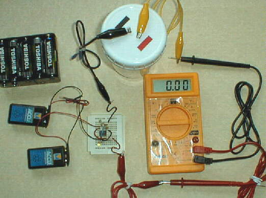
 The basic setup uses 3 9-volt batteries connected "in series", meaning they are daisy-chained one after another, to produce about 27 volts. Current flow can become excessive as the "conductivity" inside of the C.S. generator increases, however, so adding a 28 volt, 40mA rated incandescent bulb "in series" is also recommended at this operating voltage, to limit the maximum possible current flow through the system to ~40mA (milli-Amps, or thousandths of an amp.) The 8 ounce glass jar shown here has a plastic cover, with 2 holes drilled 1/2" apart, so the two "electrodes" can extend through, and be held in position parallel to each other inside. The electrodes extend to within 1/4" of the bottom of the jar; in the setup shown , when the glass jar is filled within 1/4" of the top edge, there's about 3-1/4" of wetted length.
No housing or project box is shown in this photo; if you wish to add a housing, and an ON/OFF switch, you can do so, but you can just tape the 3 batteries together, and disconnect the 3 battery snaps when you're done to turn it off... it doesn't have to be any more complicated than that!
Note that alligator clip test leads are used to connect between the parts, and a bare alligator clip is shown connecting one battery lead to one bulb lead. Radio shack should be able to provide most of the parts we'll show on this page, while Mouser Electronics supplied the bulb shown in the photo; you can read their info in the larger version of the photo.
[Note: If you don't yet have a CS generating container to use, you may want to consider using these layout measurements. Later, when we talk about using a digital multi-meter to monitor the current flowing through the system, if you are using electrodes laid out exactly the same as this, we'll give you numbers to get the same results every time (-a known product measured in Parts Per Million of Colloidal Silver.) Sources for the TDS1 meter and inexpensive digital multi-meters will also be listed in the "SOURCES" section.]
With this setup, you may need to stop and test the CS concentration to know how much you've got; some people say, "run for so many minutes from the time you see bubbles starting to rise from the electrodes", and on a shoestring budget, this will work.
What I'm working toward, however, on this web page, is an "evolution of design", if you will, which you can assemble yourself, and which will allow you to produce quality CS in your own home. I'll offer a method going along with it to monitor the progress of the process, to know when to stop your generator to have the same concentration of CS in your final product every time.
[ 1 ] Because of the increasing current limiting by the bulb as the current flowing through the generator increases towards it's 'incandescent' state, you can't monitor current flow itself through the entire system to precisely indicate the conductivity and thereby the CS concentration. ( M. G. Devour talks of monitoring the decreasing voltage across the two electrodes themselves, to have an idea where he's at in the process. I'll describe and explain a different approach.)
[ 2 ] When using a 'constant current DC supply' as is provided with the three battery setup shown above, many report problems late in the generating process when silver "sludge" (which normally forms on the negatively charged electrode) can bridge between the two electrodes, shorting out the generator.
[ 3 ] There is more and more speculation now that high currents may not produce as small a CS particles as a lower current operation. Further testing will give us more information on this subject. (We want small CS particles.) We have also observed that Hydrogen gas evolution at the negatively charged electrode, and Oxygen gas evolution at the positively charged electrode, can become rapid enough to redisperse silver 'sludge' back into the water when current becomes excessive for a given amount of electrode surface area. The result is a "cloudy" batch of CS, which we most likely would wish to avoid, as some of this redispersed sludge particles are too fine to remove with the normally used coffee filters.
Going Beyond These Possible Shortcomings
[ 2 ] Rather than a constant current, why not interupt the current repeatedly / often? The observed result is that there is no tendancy for bridging of the silver "sludge" between electrode even at only 1/2" apart. (Note that, the closer the two electrodes are together, the lower the resistance of the water / CS solution between them.)
[ 3 ] Current Levels are directly related to applied voltage levels for a given electrode geometry; by working with a PULSED DC Supply, at from 12 to 18 volts maximum, current flows are not excessive, and do not need to be limited. More on this later.
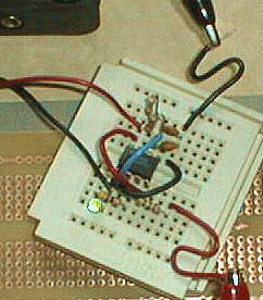
 Providing a high enough frequency pulsed DC supply for our CS Generator isn't that complicated. Here's an example of a working model I put together in a few minutes, using an "Experimenter's Socket" and a few components, all available from Radio Shack. Note that this circuit is being powered by 2 9-volt rechargable batteries in this photo.
The core of the circuit is the versatile 555 timer IC, an 8 pin DIP IC that's widely available.
The 'Experimenter's Socket" has rows of holes radiating out from each IC pin, giving 5 contact holes in each row that are internally connected together. You insert the IC into the center of the socket board, straddleing the gap in the center, then insert components one by one, until all parts are in place. This circuit also requires 3 "jumper wires", shown in red, blue, and black. These each connect points in the circuit that need to be connected together.
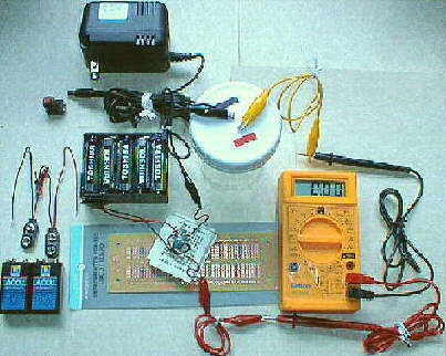
Below the Experimenter's Socket is shown a Radio Shack printed circuit board to match the Socket's layout, for those who want to solder together a permanent version of the circuit.
Note that 18 volts is the maximum that the 555 IC will tolerate, which is plenty for generating Colloidal Silver.
1----- 555 or 7555 Timer IC, 8 pin DIP package; (note that the 7555 is the CMOS version, and is static sensitive.)
1----- High Efficiency T1 size LED (green or red, your choice) for the 'Pulsed Output Active' indicator
2----- .01 uF (micro-Farrad) ceramic disc capacitors
1----- 4.7K 1/4W 5% resistor (LED current limiter resistor)
1----- 3.3K 1/4W 5% resistor
1----- 1.0K 1/4W 5% resistor
1----- 75 ohm 1/4W 5% resistor
2 ----- 9 volt battery snaps
5----- Insulated Jumper wires - single solid conductor strand, ~ 22guage ; 5 pieces 1-1/2" long is plenty for the 5 required jumpers, as shown in the photos. Strip 5/16" from each end of each jumper. Note also that two of these wires with 'S' shaped bends are shown in the photo; These are the two outputs. The red wire goes to the silver 'anode', through the meter if you use one, while the black is where the lead to the 'cathode' connects. If you only have one color of insulated wire to work with, be careful! {GRIN}
3----- Alligator Clip Test Leads, used as shown in the photos.
NOTE: Optional but highly Recommended: a meter capable of reading 20mA DC current; any small meter can do this. An inexpensive (under $20.00) meter is shown in these photos.
Note: if you can't get a 'high efficiency LED as called for and end up using a standard T1-3/4 size LED, then use a 680 ohm resistor in place of the 4.7K resistor that's used normally with the T1 'high efficiency' LED; otherwise, the larger LED won't glow at all! {GRIN}
Also, if you do not have a CS generator container yet, I'd suggest:
1----- 8 ounce glass jar, and plastic cover as shown in the photos
2----- pieces .999 fine silver wire, 3-3/4" length minimum (or strip/sheet, etc.) Note: only one electrode, the positively charged one, actually produces silver ions; the second negatively charged one donates only electrons to the process, and can be made of a good grade of stainless steel. I personally use one 14 guage (1/16" diameter) silver electrode for the 'ANODE', and one 1/8" diameter stainless steel electrode for the 'CATHODE'. Just remember to hook the positive output to the silver anode, and the negative wire to the stainless steel cathode. In the photos, you'll see red tape marking the anode, and black tape marking the cathode, to avoid any mixup.

[1]-- Insert IC in Experimenter's Socket. (Hint: we'll be using three other rows of contacts, other than the 8 rows which the IC pins use.)
[2]-- Insert 1st jumper : from IC pin 4's row to IC pin 8's row, in the next hole out in each row, right next to the IC pins. (red in photo)
[3]-- Insert 2nd jumper: from IC pin 2's row to IC pin 6's row (light blue in photo)
[4]-- Insert 3rd jumper: from IC pin 1's row to the inner hole in the unused row next to IC pin 5 (black wire in photo)
Trim leads shorter on components if desired; leave 3/8" minimum length to insert into each hole; shape leads as needed.
[5]-- Insert a .01uF ceramic disc capacitor: one lead in IC pin 5's row, the other lead in the (3rd / black) jumper's row just next to pin 5's row.
[6A]-- Insert the second .01uF ceramic disc capacitor; one lead goes in IC pin 6's row, second hole next to the IC pin; the other into (3rd hole in the row) in the 3rd / black jumper's row, the same row where you just put the other capacitor's second lead.
[6B]-- Insert another jumper: one end into the 4th hole in the same row with the end of the (3rd/black) jumper and the two capacitors' leads. This is the Black "S' shaped lead in the photo, and will serve for a ground connection point for the alligator clip test lead going to the CS generator's 'cathode' electrode.
[7]-- Battery leads: decide which power option you're useing. If you're using the '2 nine volt battery' setup,
[7A]-- Take the red lead from one battery snap and the black lead from another battery snap, and twist the wires together very tightly. Insulate this joint with tape, etc. (Note: if you're working with another supply follow on:)
[7B]-- Take the free RED wire end, (or your positive supply wire from a different battery / transformer supply) and insert it into the 3rd hole in IC pin 8's row .
[7C]-- Insert the Black remaining battery snap lead (or your negative supply wire from a different battery / transforemer supply) into the 3rd hole in IC pin 1's row.
[8]-- 3.3K resistor (orange, orange, red, gold) : Bend one lead 180 degrees = back next to the body, and cut both to ~1/2" off the resistor body end, so they will both insert an equal depth. These leads then insert into IC pin rows 6 and 7 (use the third hole in each row), with the resistor body standing upright.
[9]-- 1K resistor (brown, black, red, gold) bend one lead back next to the resistor body, same as the last one, and trim to length. Insert leads into holes in IC pin rows 7 and 8, using the 4th hole in each row, with this resistor body also standing upright. (Note that a value of 680 ohms is shown on the circuit diagram for this resistor; the 1K works well, bringing the 'duty cycle' closer to 50%, i.e., about 56%)
[10A]-- 75 ohm resistor (violet, green, black, gold): holding the resistor body horizontal, bend each lead 90 degrees down and cut each off 1/2" from the resistor body. Insert one lead into IC pin 3's row, 3rd hole ; the other end goes into an un-occupied row to the right; I used the 3rd row away from IC pin 4's row, because that's where the lead naturally lined up.
[10B]-- Add one end of the last jumper wire into another hole in the same row as the second lead of the 75 ohm resistor you just installed. The free end of this jumper wire (the red 'S' shaped wire in my photos) will be the attachment point for the positive pulsed output going to the silver anode electrode on the CS generator container.
(Note: If you use the meter to monitor the current as recommended, then an alligator lead will run from the bare end of this (red S shaped) jumper to the red lead on the meter; another jumper (yellow in my photos) will run from the black meter lead tip, to the silver anode.)
[11]-- 4.7K resistor (yellow, violet, red, gold) : bend both leads 90 degrees down as with the last resistor, and trim leads to 1/2" length. This resistor is to run from the 4th hole out on IC pin 3's row, to the 4th hole out in the empty row just next to IC pin 1's row.
[12]-- LED: as supplied, one lead is shorter than the other, and there'a a small flat on that same edge of the plastic housing. This is the lead that has to go to (ground) the 5th hole in IC pin 1's row. The LED's other lead goes into the 5th hole in the row just next to IC pin one's row; in other words, in the same row as the (left) end of the 4.7K resistor.
CONGRATULATIONS! You've made it through the circuit assembly! To test it, connect your battery / batteries; the LED should glow. A volt meter across the two output leads (the 'S' shaped jumper wires) should read roughly half of your battery supply voltage, since the output is on roughly half of the time, and the meter 'averages' what it 'sees'/ reads.
A solar powered unit is certainly another possibility- especially considering the low current demands of this process; but please, keep your CS generator container out of the bright light. (An amber bug bulb in your work area is best for those who really want to experiment with avoiding light deterioration during the generating process. Photons striking silver ions are said to disrupt / strip their positive charge, according to my information, so you probably want to avoid this as much as possible for the "must effective" CS product from your generating operation.)
You may decide to build the entire circuit into a project box. A piece of large heat shrink tubing will keep components in the Experimenter's Socket from being jarred loose. The other option, after you test this design and decide you like it, is to mount the components permanently into the matching printed circuit board from Radio Shack, and use the E. Socket again for another design project.
{GRIN} Yes, what you have is a classic fixed frequency Clark Zapper circuit; it's output is a pulsed DC square wave, exactly as Hulda Clark recommends. It can be powered with from 9 to 18 volts for 'Zapping'. You need two hand pieces; two pieces of copper tubing will do; or you can get a couple of pieces of stainless steel, tube or flat plate....
Some people find the current output (when using the 75 ohm resistor between the IC's output at pin 3 and the actual output wire) a bit "hot" for their preferences. If this is your experience, you can replace the 75 ohm resistor with a larger value; the classic 'Clark Zapper' as featured in Hulda Clark's Book, "The Cure For All Diseases" uses a 1K ohm resistor in this position; something in between may suit your purposes.
Please keep in mind that this is an experimental pulsed DC frequency generator. What YOU choose to do with it is totally within YOUR control!
UPDATE: Another tip: by changing the value of the timing capacitor (between pin 6 of the IC and ground) to a larger value, this device will produce a lower frequency. By using a larger value of resistor between pins 6 and 7 on the IC, you can lower the frequency. (Lower values produce higher frequencies). For instance, if you use a .1uF capacitor, and a resistor of around 470K Ohms, it will produce a pulse rate of around 15 Hz. By using a 390K resistor and a 100K trimmer in series between pins 6 & 7, you could fine-tune it to exactly 15 Hz, or 15.2 Hz, for example, using a precision frequency counter.
If you wanted to limit the output through a direct short to only 5 mA, you would a series resistor coming from the IC's output , at pin 3, determined in the following way: take your power supply voltage ; let's say it's 12 volts; divide it by .005 amps to get a required resistance value of 2400 Ohms, or 2.4 K Ohms.
If you tried to measure current, you'd read around 2.5mA, since the square wave output is on half of the time, and off half ot the time, while your meter 'averages' what is being input over a longer measuring period to give you the averaged value.
Designing to Overcome Possible Shortcomings | No Soldering Required | Project Parts List
Circuit Diagram | The 'Experimenter's Socket' | Assembly Instructions
10 Cell Power & Other Options |
CS Making Instructions | 'Oh, By The Way'
 The HTML Writer's Guild.


NO WARRANTY OF FITNESS FOR A PARTICULAR USE IS EXPRESSED OR IMPLIED! This is an experimental device, a low voltage, very low current pulsed DC frequency generator; what you choose to do with it is up to you, within your control. It is believed by many that a device such as this, at this low voltage and current, is at the least not capable of producing any harm. (Stimulation of detox reactions may be one possibility in some sensitive individuals, as pathogens are "Zapped"; refer to the book mentioned previously, or to the websites referenced for further details.)
This material provided on this website and included with these kits or completed units is provided for informational purposes only, as reports of experimental uses by others, and should not be considered as medical advice. It is supplied so that you can make an informed decision. Please consult with your health practitioner before considering any therapy or therapy protocol. The author of the book "The Cure For All Diseases" is a Ph.D. and N.D., so I also would like to refer you once again to that book for a more thorough understanding of how this device can be used as the "ZAPPER" referred to in it. Also, for further info, the published works of Dr. Robert Beck and the books of Dr. Robert O. Becker, M.D. including "The Body Electric - Electromagnetism and the Foundation Of Life" are well worth researching, among others.
"{d} Licensed practitioners, including physicians, dentists, and optometrists, who manufacture or otherwise alter devices solely for use in their practice."
"{f} Persons who manufacture, prepare, propagate, compound, or process devices solely for use in research, teaching, or analysis, and do not introduce such devices into commercial distribution."
It is in the spirit of the above 'exemptions from regulation' that the circuit diagrams, projects, kits, and experimental devices offered here for research purposes can be made available to everyone for use in their own research, allowing each of us the opportunity to take charge of our own well-being! This, combined with the First Ammendment protection of our rights of access to information (freedom of speech), are the basis for the availability of the research information you will find here.
Also note that I take a break from producing this research equipment each year during February, March, and April, so that I can take care of personal businees and devote more of my energy to my own research and well-being. Any requests / orders submitted during that time period will be completed after I return to production work in early May.
