Project started on January 5th, 2008; material was last added to this page on 5-28-2009; Thanks for visiting!

This stylized rendition of a "Zarkanian Scout Ship" is my own origional design. (Official Sources decline to either confirm or deny the existance of similar-appearing craft flying in the airspace over our planet, despite repeated reports of sightings of "UFOs" in the South Park and San Louis Valley regions of the Central and Southern Colorado Rockies, as well as in other regions throughout the last 55 years.)
The Zarkanian Scout Ship is likely one of the easiest-building RC aircraft I've designed to date... and it flies superbly! You may want to build one for yourself! I'll provide enough in the way of plans and instructions so that a modeler should be able to do that. The base design criteria is to KEEP IT LIGHT & SIMPLE! The material you use will have a bearing on the weight, structural strength, and longevity of your Zarkanian Scout Ship. It's all about trade-offs, with a certain flight performance envelope in mind.
This just might also be one of the best candidates for setting up as a night flying LED lighted "UFO" type design. I'll also write up the information for doing that as time allows. (I may also design a lightweight mono-ski for flying from & landing on softer snow, that will mount on the simple front landing gear.)
MATERIALS & EQUIPMENT
The entire structure can be built from less than one 2'x4' panel of DOW Bluecor or other fan fold foam material, and could also be built with Depron, or another RC foam material you have on hand or have access to. It is sized so that the main 23-9/16" long wing panel can be cut cross-wise from a panel of fan fold foam such as Bluecor. I'll be showing photos of my build using both Bluecor PP, and also another 6mm foam board with plastic surface film on top & bottom surfaces, which has enough rigidity to not require the addition of hard (CF / bamboo, etc.) cross-wing spars. I discovered, in the process, that the Bluecor PP is 7/8 ounce LIGHTER than the white plastic covered foam board... so for a lightweight indoor flyer, it's my choice. Conversely, if you want to do an elaborate graphics trim-out and you don't mind the extra weight, , the white material would be a very nice material to use. The following photos will show both materials; I'll likely finish out the Bluecor PP version first for my own use.
You will need a radio system that has elevon/ delta mixing capability. (Having exponential rates is also very helpful for easy smooth flying.)
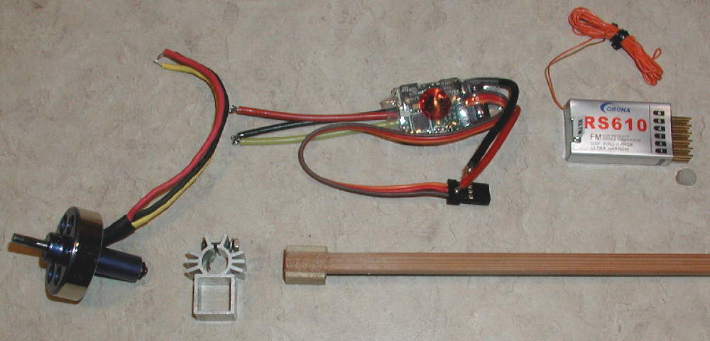
The Zarkanian Scout Ship uses an inexpensive 16 gram or 24 gram brushless motor, 10 to 12 Amp brushless ESC, and a modest priced 2S 900 mAH LiPoly battery. It also uses a lightweight 4 or 6 channel receiver and two inexpensive 5 to 9 gram servos. (The extra channels on a 6 channel receiver can be used to control a more elaborate LED lighting system; otherwise, a 4 CH receiver will do fine.) www.Lazertoyz.com is one source within the U.S. which offers decent prices and fast shipping on most of the power system items; I've dealt with them several times.
I use 1.5mm CF rods for the elevon linkages with 1/32" music wire ends. I have obtainined these from BPHobbies.com and RCFoam,com at good prices; some other hobby suppliers also have similar products available. The landing gear strut is made from a piece of 1/16" music wire- plenty of support for this light of an aircraft.
On this 'Fantasy Scale' design, I've chosen to design a high stability aircraft with large wing tip plates that work not only as vertical stabilizers, but also work as dual wide stance tail skids in conjunction with the single forward wheel, to provide excellent ground handling for both takeoffs and landings. This also offers excellent protection for the propeller and motor.
The elevons are sized nicely to provide excellent control. The upper and lower profile fuselages were designed to both add to the visual impression of a "UFO" inspired craft, as well as to contribute to the structural stiffness in the longitudinal direction.
This design has the lightweight motor mounted well forward from the ideal CG point, giving more room between the motor and the CG point to move the battery forward and back to easily achieve balance. (There's no tricky balancing act involved with this design, when built according to my plans.)
The wing is made from a single layer of 6mm foam; I laid out one prototype from material which was supplied in a 19-1/8" x 25" sheet. It has a white foam core with a plastic surface film on both top and bottom. It is lightweight yet strong, and has enough rigidity so that no span-wise spars were required. Scotch brand cross-filament nylon filament tape was used spareingly in a couple of locations to add what strength is required.
For the second layout, I used Bluecor PP; the underlying emphasis on this design is to keep it light so that it can perform at very slow flying speeds, and the Bluecor PP fas a substantial advantage over the white foam panel which I first cut out.
On 2S LiPoly batteries, the performance of the 1300 kV 24 gram brushless motor should be ideal when flying with a GWS 9x4.7 Slow Flyer propeller; I'm using that setup on somewhat similar size / weight aircraft. For higher speed flying, a 1700 Kv motor could optionally be used.
[When using the 16 gram 1700 Kv motor from Lazertoyz.com, I flew with a GWS 8x4.3 slowflyer prop.]
With the 2S pack and larger lower pitch prop I'm using , the Zarkarian Scout Ship should be able to be flown at reduced throttle settings in a limited amount of space , so it should work very well as an indoor flyer.
Using a 10x3.8 prop might also allow irreverently slow maneuvering while maintaining excellent thrust in indoor & outdoor slow flying situations. Conversely, changing to an 8x5 or 8x6 propeller should kick up the top speed, and the roll rate as well. These options will be tested as time allows.
The Zarkanian Scout Ship is designed to be an *Excellent* night flyer- it's that stable and predictable! I'll be installing the LED light system, and including information on my setup as the build progresses..
Keeping this build simple was a priority, and it's really a quick and simple build. Below is a photo of the one sheet plan drawn on 1" grid paper for the main foam pieces.


After the top fuselage piece was shaped in a pleasing manner, I duplicated it for the bottom, but made the two separate forward pieces to form the side panels of the battery compartment. Final trimming of the three bottom pieces will be done during assembly. (The lower rear end of the lower fuselage will also be trimmed further to provide ground clearance, so that with the landing gear mono-wheel in place, only the two wing tip panels' lower rear ends touch the ground.


Next, I made up the motor mount. I'm using the aluminum stick mount for my 24 gram 'Blue Wonder' motor, and from 4-1/2" to 6" of the heavy / square end of a bamboo chopstick for the main motor mount shaft. I used a 1/2" long piece of 10mm square stick as a spacer to fill out the motor mount, and notched it out to fit the bamboo chopstick. These were glued together before being fit into the motor mount. Later, two small screws will be used to lock the motor mount on the stick.
Before doing any assembly / gluing, I marked out the center 1/4" (6mm) wide area on top & bottom where the motor mount and top and bottom fuselage pieces would be mounted. Next, rather than trying to cut and strip away the plastic surface film in this area (which would possibly weaken the structural strength of this sheet foam) I 'woodpeckered' holes in the area so that the glue would penetrate into the foam core and bond solidly.


Above: I then mounted the motor mount stick in place on the wing's lower surface with 5 minute epoxy glue. (This is a 0-0 setup- no offset thrust lines, and with the motor mounted as close to the wing panel's center line as the mount allows.)

The Balance point / CG is at 9-5/16" back from the front edge of the 23-9/16" long foam panel. Mark this line at the center, top & bottom, for use when deciding where to place the battery for proper balance.
If you are using FFF Bluecor PP or especially the single surfaced 'protection board', you may want to do more to stiffen the wing laterally. I added 1mm CF rod 'spar caps, on both top and bottom, to keep the wing panel flat and stiffen it substantially- all while adding only .02 ounce of CF material. I placed this on a line crossing through the balance point; I made a shallow rounded depression in the surface of the Bluecor without breaking the plastic surface skin, then "woodpeckered" a line of pinholes, spaced ~3/16" apart, along the length of this depression. I then used foam-safe CyA glue to glue it in place; the glue penetrates through the surface film via the pinholes to bond these spar cap rods deeply into the foam core. I weighted it down flat with three surplus batteries, & sprinkled in a very conservative bit of baking soda, a bit at a time in various places, to set the CyA glue. Once the first one was completly glued in place, I turned over the wing pannel and repeated the process directly over the first CF rod spar.

Next : The elevon leading edges are cut and beveled for top tape hinging. I use 1/2" wide Scotch transparent 'multipurpose' tape on the top, and use 3/4" wide tape on the bottom / bevel side. It's best to leave about a 1/32" space between the aileron L.E. and the wing's T.E. when applying the top surface hinging tape; that way, after the under-side tape ias applied, the hinge line does not bind, and the hinge will flex freely.

I weight down my pieces while applying the hinging tape so that the parts do not move while the tape is being applied. The following photos show the process and results.

[Above:] This photo shows the how the wing is positioned with the elevon folded back after the top surface hinging tape has been applied, so that the under-side 3/4" wide tape can then be applied. the two pieces of tape adhere to each other in the 1/32" wide hinge gap area.

[Above:] Here's a look at the underside of the elevon hinge line after the tape application is complete, showing the cut-away bevels.

[Above:] Here are two more upper fuselage pieces; these were also laid out and cut out across the 24" dimension of the Bluecor fanfold foam panel, to avoid the 'ripple' that is present if these pieces are cut along the 48" axis of the FFF sheet.

[Above:] Lower fuselage pieces glued in place. (Old Gel Cell batteries make great 90 degree glueing blocks!)

[Above:] Glueing upper fuselage piece in place

[Above:] Wing end plates / (tailskids) glued & pinned in place

[Above:] Side profile after all foam parts are assembled
[More soon]
The ZARKANIAN Scout ship ("ZARK" for short) is ready for a maiden flight now. I mounted a 2211-17 motor (called a "16 gram, 1700 Kv" motor by Lazertoyz.) It's rated as a 70 watt motor. I'm flying one of these on my FLIRT, and it has so much power to spare, that I thought it would be more than adequate for the ZARK. The motor mount uses a reducing sleeve to mount the 6mm motor rear bearing housing; with the motor out and this reducer spilled out, it will mount a 24 gram 'Blue Wonder' motor in the same motor mount- kinda handy if I ever want to kick up the power / speed on the ZARK! :D
The rudder on the ZARK is an added control surface that was never used on the OMEGA or ACE designs; I'm looking forward to playing with it! I'll post a report before long.
With the components all mounted well forward, the battery mount position is centered on this aircraft's balance point, so a wide variety of batteries of different weights can be carried in the same mount location. When using a 2S 460 mAH pack, and with a GWS foam wheel mounted on the mono-gear, the flying weight is only about 6-3/4 ounces at this point (before installation of the lighting or any trim.) With as much wing area as the ZARK has, it should be able to fly very slowly when desired, and do well indoors.

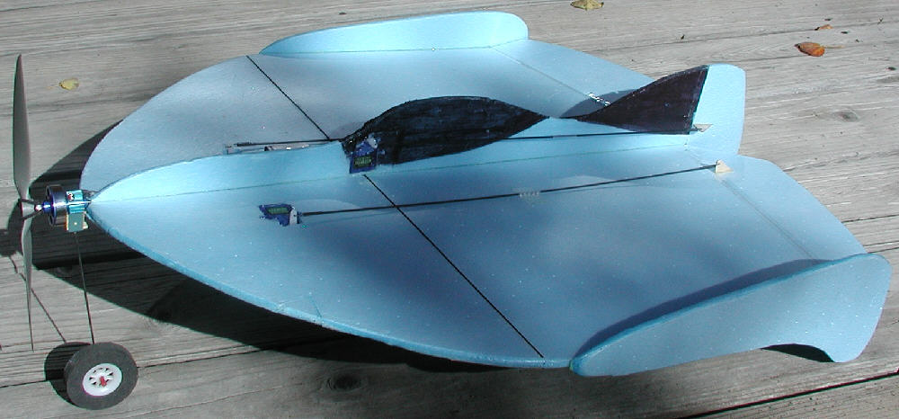
[Above:] Ready for maiden flights!

[Above:] I installed all three HXT500 servos and radio receiver well forward. I also installed a front 1/16" music wire mono-gear for mounting either a wheel or a ski, similar to what has worked so well on the Manta ACE. Linkages are 1.5mm CF rods with 1/32" music wire ends & heat shrink couplers, with a center support tube- they provide very posiitive control, yet are very light weight.
I used a CORONA RS610 receiver for the ZARK so that I'd have both the landing gear switch and the flap switch to control up to three different lighting functions.
I also did the base loading trick on the receiver's antenna; the completed overall length of this antenna in not much over 6". I'm already flying three others of these modified antennas on the FLIRT and on my two SUMOs, and they handle glitch-free at out to ~450 to 500 feet from the transmitter so far.

[Above:] I haven't completed enclosing the underside electronics & battery compartment yet; I'm waiting until I get the wiring installed for the LED lighting system. All of the extra servo leads get tucked away there, along with the lighting electronic switches. More details will be posted as this aspect of the project progresses.

[Above:] Upper top front view.

[Above:] With the 1/32" birch ply ski mounted, and a 2S 900 mAH ABF battery on board, flying weight is at 7-3/8 ounces.
The trim out work will be saved for last, after all of the wiring for the LED lighting system is in place.
The fun continues... go ahead- fly something that looks 'Out Of This World"!
UPDATE: on May 28, 2009 I mounted the 24 gram 1700Kv motor, and am flying an APC 7x4 prop on the initial test flight, and using the 2S 900 mAH LiPo pack. Speed is noticably faster! An APC 7x5 prop is also on hand, available for testing. With the mono-wheel landing gear removed (for landing in tall grass) the present flying weight is at only 7.5 ounces- light weight for this large of a wing area.
It's time to finish enclosing the lower forward battery compartment, and then to add some trim!
For night flying with an LED setup, I'll likely swap back to a ~1200 Kv 24 gram motor, turning a larger low pitch prop, for more relaxing night flying.
Seoptember 26th, 2009: This morning I tackled the rudder re-design on the Zark. The photos show the process & results. I'll report on the flight response later.

Above: ZARK with material cut away, ready for new rudder which extends both below & above the elevons

Above: New rudder; it has more material below the wing deck to balance out the affects on the aircraft

Above: New rudder hinged in place with linkage; has clearance for ROG takeoff with tall front mono-wheel gear.
Above: ZARK with new rudder, ready to fly. Mono-wheel works fine under the front. Flying at 7.7 Ounces
9-27-09 : MANTA ZARK continues to go through tweaking! After flying with the new rudder, I observed that there was too much vertical stabilizer affect on the aircraft from the large wing tip plates. (GPW had talked of trimming down these on one of his earlier designs, too.)
So this morning I decided to start to trim away some of extra wing tip plate foam. The photos show the new slimmed down profiles.
Weight also dropped to 7-3/8 ounces; making an aircraft lighter is always good!
Winds were gusty to ~20 MPH on the first test flight, so I did not fly for too long. I'm noticing that the roll rate is increased with the trimmed down wing tip plates. I expect that the rudder response will also be increased. I'll be doing more test flying soon- the gusty winds seem to have died back some now.
For dealing with the stronger gusty winds, I'm flying a GWS 8043 Slow Flyer prop; it penetrates better than when flying the 8x3.8 APC, so it handles the wind better. That's the nice thing about prop savers; you can swap props so fast, depending on the conditions or the type of flying that you're in the mood to do!
[Above:] The ZARK after the rear vertical fuselage structures were modified and the new larger rudder was added , and the wing tip plates were trimmed down to allow for better roll response and rudder response.

OK, Mission Accomplished!! The Manta ZARK now hasr rudder authority to flat spin very effectively!! I kick in full left rudder, use a LOT of up elevator, and use oppsite aileron to flatten out the flat spin. And it'll do it in strong gusty winds, too - no problem!
Drop the sticks back to neutral, and it recovers immediately- which tells us that there's still plenty of vertical stabilizer area for about any type of flying you could imagine!
Love it when a design gets evolved into a REALLY capable flyer!!!
A Blue Wonder 24 gram motor in the 1700 wind has fewer wraps per pole of a heavier gauge wire; this translates into it's being capable of handling more peak amps without heating up than the 1300 wind motors can handle. Right now, on the 2S 900 packs, the GWS 8043 SF prop offers enough speed & penetration to handle the winds with no problem, and offers unlimited vertical performance if you want it.
When the wind isn't blowing much, It also can fly very slow in high alpha attitude if that's what you like, too. Oh- and even with the balance forwward where it has good stability dealing with high winds, it'll still do continuous repeated tight loops in about it's own length!
If you use a 6 channel receiver, rather than a four channel one, for controlling your Zarkanian Scout Ship, you have both the landing gear switch (CH 5) and the Flap switch (CH6) an six channel transmitters that are not needed for basic flight controls. That gives you two channels of lighting control for night flying. I did a quick Google search for a dual RC switch that I could operate from each of these channels, and came up with this one. (There are likely other sources for such products; I liked the fact that this one is very compact, and weighs ony 4 grams, including the servo connector, and uses two sets of pins for the two outputs. I can use a dual switch on CH 6, and even add more switchable lights on CH5 controled by a second switch if I choose... and I can still have some LEDs which are on full-time, powered from CH4 on the receiver, too. This offers about as elaborate a combination of lighting switching options as I'll ever need!

"This is a miniature DUAL RC switch for handling loads up to 2.5A per switch. The control of these switches are unique in that they only need a single channel to operate both switches. The state of each switch depends on the position of the stick (or the programmed lever position on the transmitter). When the switch is closed, the supply voltage (absolute max is 6.0V) appears across the positive and negative output pins. This is suitable for driving strobes, high-bright LEDs, lights, smoke systems, or 5V relays. Can be configured as a single RC switch if needed."
Load rating : 2.5 amps max per switch (@~5V)
An RC Servo lead (6" long) is already soldered to this unit- you do not need to do any soldering! Connector is universal Futaba/JR style.
Simple to set up, read the data sheet , accessible from this web site, for further information.
Price: $14.49 each plus shipping; I paid $6.20 for shipping on two.
[Right-click on this link & select "Open Link In New Window":] Here's one good source for LEDs: SUPERBRIGHTLEDs.com I'll be working with specific products available from them in setting up all of the lighting on my Zarkanian Scout Ship.
<>P[TECH NOTE:] Different LEDs from different manufacturers can use differing chemistry, have different 'forward voltage props', and require different resistor values to limit current to safe levels. If you use the same specific LED products I have tested and use, the values for the current limiting resistors that I specify after my testing will work well for you, too. If you have other LEDs from other sources and manufacturers, and want to set up your lighting system with those, then the additional information I had written previously on my NIGHT FLYING web page should be helpful to you.
If you are handy with electronic circuitry scratch-building, and wanted to build your own single channel RC switch (using one 4013 CMOS IC), the circuit on THIS WEB PAGE is one possibility. It's offered by Tony van Roon, who has a link at the bottom of that page that will take you back to his "RC GADGETS" page.
This web site and all of the digital photos and other original materials found here are subject to protection under the Copyright laws; All rights are reserved by Bruce K. Stenulson, P.O. Box 69, Fairplay CO. (c) 2004-2009. Permission is granted to link to this web site or to it's individual pages, but not to reproduce any materials found here for other than personal, non-commercial use. My intention is to maintain the context within which this material has been presented.Thanks for your understanding.