With the recent increase in the availability (and the drops in prices) of Super Bright and X-BRITE LEDs, night flying lighting setups are now able to be designed using these high efficiency devices. But there's a lot of technical details you need to understand before you buy components & start wiring them together. I've written the following material to try to help you over the "hump in the learning curve", and hopefully get you on your way to night flying success.
BACKGROUND INFORMATION TO START
LEDs are 'Current Sensitive' devices, and almost all of the T1 and T1-3/4 sized ones are specialized semiconductor devices made to handle up to 20mA of continuous current, which is the current level where their rated output light intensity is produced. So the current flowing through each LED must be limited, so that it never exceeds this 20mA level. (LEDs are destroyed by too much current.) Current also will only flow in one direction, so these are 'polarity sensitive'. The "Cathode" goes towards the negative side of your voltage supply, and you can tell which lead that is by looking for a small flat area along the lower rim of the LED plastic housing next to the cathode. The other lead on a diode is referred to as the "ANODE", which goes towards the positive side of your voltage source.
All semiconductor diodes, including Light Emitting Diodes, also have a "forward voltage rating", which comes into consideration in setting up a LED night flying lighting setup. An LED's 'Forward Voltage rating" is defined as the voltage level at which 20mA of current will flow through the LED, producing the maximum rated light intensity that can be continuously produced without damaging the LED.
(If more voltage is applied than this 'forweard voltage rating', more current will try to flow through this semiconductor device, unless we limit it to a safe current flow level. This means that we need to either limit the voltage to exactly the right level (which varies for each specific type of LED's semiconductor composition) or else we add extra devices to provide a 'current limiting' function. )
When working with a battery supply for an LED lighting setup, it's rare to have exactly the supply we want, so we have to accomplish the current limiting by adding either 'voltage reducing' devices or 'current restricting / limiting' devices in series with our LEDs.
Rectifier diodes, such as the commonly available 1N4004, also have a very predictable forward voltage drop, and so they can be used to 'step down' the voltage going to the LEDs. Each 1N4004 diode placed in series steps down the voltage by .193 volts. When rectifier diodes are used in this way, I refer to these as 'voltage dropping diodes' or 'voltage reducing diodes'.
I use 1N4004 diodes as voltage dropping diodes, to to reduce the voltage from the supply and thereby limit the current through the LEDs; any electronics supplier will carry these. How many voltage reducing rectifier diodes you might need to use is always relative to the specific LEDs you have chosen to use.
As an example, if I'm using 2 diodes to reduce voltage to a group of red LEDs, I solder the two diodes together in series in the wire from the 4 cell battery's positive supply wire, with the banded ends of the diodes away from the battery; I solder a green and a yellow wire after the first diode to supply all of the green and yellow LED sets (when using the diodes who's parrt numbers I've noted below) , and the red wire after the second diode, which then supplies all of the red LED sets.
'Current Limiting' can be accomplished in either of two ways: by adding 'voltage dropping' diodes, or by adding current limiting resistors in series with the LEDs. Resistors produce heat when limiting current; they are rated by size in WATTS for the amount of heat they can handle / dissipate. Here's the part of Ohm's law that is used to calculate what wattage rateing a resistor must be to do a certain job: [ V x A = W ] Volts times Amps equals Watts.
For very low current applications, a 1/4 watt resistor of the right resistance is adequate; as an example, to limit current to 20mA through one pair of yellow LEDs in series, powered by a 4 cell NiMH supply battery, we have a maximum supply voltage on a fresh charge of 5.5 volts, x .020 Amps, = .11 Watts. This tells us that a 1/8 watt resistor would just barely get the job done, and a 1/4 watt resistor would be very adequate, as far as handling the heat dissipation job.
For higher current flows, however, sizing of the resistor (wattage rating) is selected depending upon the total current you are passing, and hence the required heat dissipation. For example, my wing with 12 LEDs ideally has 6 pairs drawing 20mA each, or a total of 120mA of current from a supply battery tha sources up to 5.5 volts on a fresh charge. That calculates out to .66 Watts of heat dissipation required, so it would need to be sized up to the next available size, a one watt resistor.
But what resistance value would be correct for this job? To calculate that, we first need to know the difference between the total forward voltage rating at the desired 20mA current of the combined series pair of LEDs, compared to the maximum battery supply voltage (again, I tested, and use a value of 5.5 volts on a fresh charge.) If we are using LEDs with a forward voltage rating of 2,1 volts, then the combined forward voltage is 4.2 volts. Subtracting this from the supply voltage of 5.5 volts, we have a voltage differential of 1.3 volts. Another part of Ohm's Law tells us that Volts divided by Amps equals Ohms. 1.3volts divided by .120 Amps = 10.833 Ohms; so we would try to buy an 11 Ohm one watt resistor to do the current limiting job, and wire it in series between the battery and the array of LEDs in the common supply wire, and mount it where it could dissipate the heat hat would be generated when current was flowing in the circuit. (Buying a 10 Ohm, a 11 Ohm, and a 12 Ohm resistor to test might be a good idea, then testing using a current reading meter temporarily wired in series, to get a reading of the actual current in the completed wiring setup.)
As another example, to run a White LED, with a typical forward voltage rateing of 3.55 to 3.6 volts, you have to drop the excess voltage from a 4 cell pack, at 5.2 to 5.4 volts, down to a level where the LED has a maximum of 20 mA flowing through it. You can wire a series of 1N4004 diodes in series; It'll take 9 or 10 to drop the voltage below 3.6 volts. The forward voltage drop per 1N4004 diode is about .183 volts, based on a test setup I recently put together. You can work from that data to do what you need to do. (Other types of rectifier & small signal diodes have different voltage drops, so test if you are using something else.)
To do this current limiting for a single white LED with a resistor, we calculate a voltage differential of 1.95 volts, divided by.020 amps = 97.5 Ohms, and calculate required wattage as 5.5 Volts x .020 Amps = .11 Watts; so a 100 Ohm 1/4 watt resistor wired in series to each LED would be the way to keep it limited to a safe current limit of 20mA, using a single inexpensive resistor for each white LED we planned to use. (Using a separate resistor supplying each LED in multiple LED inastallations avoids unbalanced current flows.)
A "Low Dropout Voltage Regulator" with a 3.6 volt output rating might be the most elegant approach, which then is capable of delivering a regulated full 3.6 volts, and up to 3.0 A of current, throughout the discharge life of the battery pack down to 4.9V. Mouser sells this 3.6 volt LDO voltage regulator in a TO-220AB case as part number 511-LD1085V36 for $1.30, and sells the 3.3 volt version under part # 511-LD1085V33 for $1.30
~~~~~~~~~~~~~~~~~~~~~~~~~~~~~~~~~~~~~~~~~~~~~~~~~~~~
I had set up my lighting system in the "LIGHT STIK B" to use either a 4 cell 150mAH NiMH battery pack (made from 4 of the 6 cells inside an Eveready 9 volt rechargable NiMH battery) or a 4 cell 300mAH NiMH (~1.0 ounce) battery (purchased from www.radicalrc.com) for maximum intensity, and well over an HOUR AND A HALF of light time on an 18 LED setup.
Wanting a park flyer wing that I could easily use for night flying, in December of 2002 I built a second wing for my "LIGHT STIK B", set up for using 8 each of the red and green, and two Golden Yellow "SUPER BRIGHT" 5mm size LEDs. All wiring is installed inside of the wing, with small two pin sockets wired in place, so that the LEDs can simply be plugged in quickly for night flying, and removed for normal daytime flying. These new LEDs are rated at 3500 mcd each @ 20mA, many times brighter than the T1 3mm LEDs I had used in the past on my Wattsinnit. Cost varies from .45 to .99 each for these high intensity LEDs; for the maximum in visibility, they're worth every cent, as far as my eyes are concerned!
"X-Brite" (EXTRA BRIGHT) LEDs are actually available now in 10,000 mcd brightness and above, but you'll pay more for them than for the 3500 mcd brightness ones- especially in green. More importantly, some of them have a much higher "Forward Voltage" specification, which complicates the required current limiting setup, even though the current rating for these X- Bright LEDs is the same (20mA).
~~~~~~~~~~~~~~~~~~~~~~~~~~~~~~~~~~~~~~~~~~~~~~~~~~~
For a fast aircraft which covers a lot of sky quickly, EXTRA BRIGHT LEDs might be a good option, as well as for scale lighting setups, where you only have one red light on the left wingtip, one green on the right wing tip, and one white at the top of the tail. For slower Park Flyers, I'm very satisfied with the 3500 mcd brightness LEDs. On a larger plane, I'm simply adding more sets of LEDS for increased visibility / aircraft definition while it's flying in the night sky.
("Light Pollution" is another factor to keep in mind; there are few night flying sites that do not have other lights in the distance to 'mess with' your night vision; even a bright starry sky is more challenging than a cloudy, moonless night, as far as keeping track of the plane's attitude at all times, and being confident enough to do aerobatic maneuvers in the night sky re)quires a highly visible night flying lighting setup. If you can fly a slow flyer low & close, it's easier to see a sparsly lighted aircraft, but faster aircraft that cover a lot of sky at a greater disrtance simply beg for more intense lighting.
On a giant scale (84" wingspan), non-scale sport aircraft wing I'm presently working on building, I have installed sockets and wiring throughout the wing for a lot of the 3500mcd LEDs- 12 red on the top, bottom, and wingtip of the left half of the wing, 12 green on the right half of the wing, a pair of 3500 mcd golden yellow in the center of the wing's leading edge, and two more 9500mcd light yelow for 'landing lights' , as well as 2 orange LEDs on the fuselage belly, and one white on the top of the tail. Yes, it should be lit up like a Christmas tree, and really easy to see in the sky.
SOURCES AND PART NUMBERS OF DEVICES I CURRENTLY AM USING
HOSFELT ELECTRONICS (www.hosfelt.com) offers a good selection of 5mm "Super Bright" LEDs, and is one of the main sources I use.
I use 3500 mcd Green LEDs with a forward voltage specification of 2.5 to 2.8 (HOSFELT Part # 25-366 for .99 each) These can be set up in pairs of LEDs which are wired in series, with one 1N4004 dropper diode inline from the common supply to all of the pairs, to reduce the voltage so that the current through each of the pairs of LEDs is limited to a safe maximum current of 20mA.
Mouser Electronics (www.mouser.com) offers the 3500mcd (Reddish Orange) LEDs from Fairchild, (part # 512-MV8716 for .37 each,) with a 2.1 volt forward voltage rating. I use two of the 1N4004 diodes in series to step down the voltage for the multiple pairs of these LEDs wired in series. (If I were to do the current limiting for these six pairs of LEDs with a resistor, it would need to be a one Watt sized resistor; 5.5 volts x .120 Amps = .66 Watts ; you always go up to the next larger size. The resistor would also heat up quite a bit; the voltage reducing diodes are a better choice for this particular job.)
Mouser's part # for the Rectifier diodes I use for reducing voltage : ( 512-1N4004 at .05 each, $4.00 / 100)
Hosfelt also offers an 8000 mcd Red 5mm LED with a 2.0 forward voltage rating: (Part # 25-359 for .79 each) test the current of the actual wiring array, as wire losses might come into play; these may need more than the 2 1N4004 diodes to drop the voltage sufficiently so that the current is limited to a safe level.
Hosfelt offers a 3500 mcd yellow LED with a 2.3 volt forward voltage spec." (part # 25-357 for .49 each) which runs in pairs in series from a four cell pack with a 75 ohm 1/4 watt current limiting resistor to keep the current limited to 20mA.
My pair of "Landing Lights" light Yellow LEDs have a 2.2 volt 'forward voltage rating', and my testing showed that an 82 Ohm 1/4 watt resistor was needed to keep the maximum current from the 4 cell NiMH battery supply limited to 20mA.
On larger sport planes, I'll sometimes use Orange LEDs (lighter 'true orange', 605nM color) on the belly of the fuselage, to further improve definition on my aircraft; (Hosfelt part # 25-407 for $1.45 each), 10,000 mcd, 2.0 to 2.4 forward voltage rating, are the brightest that are available; a pair in series should run well with one voltage dropping diode inline on a small 4 cell pack. (If by chance you don't want them that bright, simply limit the current to a lesser value to reduce the intensity.)
Other Sources: DIGIKEY.com offers some Super Bright LEDS; www.superbrightleds.com also specializes in Super Bright LEDs.
Tech note: If you have a current reading multi-meter, you can use it to verify that you do not exceed the 20mA continuous current limit for T1-3/4 5mm LEDs. Keep in mind that 3/4 of this current, or 15mA, still gives 3/4 of the light output intensity, and with 3500mcd LEDs, that's still a lot of light, so it's not really necessary to crowd the maximum current level. It's when you do want to go for the maximum brightness without destroying the LED with over-current, that you have to be more careful. If you set up for a maximum current flow of 20mA through any LED when run on a fully charged light battery pack, as the pack discharges, you'll still have good brightness levels. The technical data sheets for specific LEDs offer graphs of the various parameters, for those who are inclined to research this aspect further.
For wire, I have found that taking apart an inexpensive computer printer cable will yield a nice collection of 18 fine insulated wires in many colors; this is what I use for wiring these lighting systems. In wiring lights into the inside of a wing before covering, I simply poke holes in the balsa with a large T-pin and thread the wire where I want it, glueing it in place with thin CyA glue.
I'm also now building in individual two pin "sockets" into the balsa structure on new construction projects, flush with the covering surface. This allows all wiring inside the wing to be completed, then the entire wing to be covered, before installing the LEDs in their "sockets". They are referred to as 'SIP sockets' with a .1" spacing, available in strips which can be divided into sets of two. [ Hosfelt carries "MAchine Pin SIP Sockets" in a 64 pin strip, part # 21-388 for 1.49 each] You can have sockets for 32 LEDs from one strip, usually enough for an aircraft setup. I use a razor saw to carefully separate the sections, so I don't break any in the wrong place.
Briefly, In most cases I now use multiple sets of two LEDs, each set of two being wired in series, set up to run directly from a 4 cell mini battery, with one or two 'voltage dropping diodes' added in the supply wire to limit current to the desired levels, as required. You can arrange as many "sets of two LEDs wired in series" as you want to use to light your aircraft, all powered by the one lightweight 4 cell lighting battery.
For a temporary tape-on set of lights on an aircraft (such as the Teddy, for instance), I would use from 4 to 8 of each color on each wing (red on left, green on right)- and possibly add a pair of golden yellow to the front center only. For taping LEDs on on, I'd leave the LED wire leads long, soldering the wires to the very tips of the LED leads, and then forming the leads into a supporting shape so they can be taped in their desired positions on the surface of the wing.
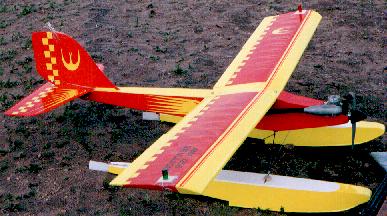
I'd originally built the E-FOX wing several years ago, before I was using LEDs for night flying lights. I had run wires from the center out to each wing tip before covering the wing, leaving the outer ends of the wires glued in the balsa outer end ribs for later access. The E-FOX wing uses Wing Tip Plates, which act as an 'air dam' and add much more lift (~46%) than drag (~16%), and improve the extreme low speed performance of the wing, keeping the airerons very effective down to a walking speed. These wing tip plates were made of poplar Lite Ply, mounted in place with 4 screws.
In May of 2004, I set up the E-FOX on floats, and it is performing very vell. I've always liked night flying with float planes... you fly towards the reflection of the plane's lights as you approach the water for a landing, which works really well for knowing when you're close to touch-down. (Night flying from snow is similar, in that the plane's lights light up the snow as you get close to the surface.)
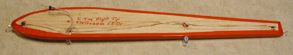
My 'bright idea' was to make a replacement wing tip plate, made of softer 1/4" balsa, and install 4 of the 10,000 mcd LEDs in each wing tip plate, with all the wiring embedded & glued into the inner surface of the balsa, and a plug & socket connector in the wires, so that the wing tip plates could be quickly & easily swapped out. So I've done just that!
For this project, I'm using Kingbright 10,000 mcd Red LEDs (Mouser Electronics part #604-L7113SECH for .82 each) I wired these as two paralleled sets of two LEDs wired in series, and did the testing, and found that I could either use a 68 ohm resistor in the supply to each set, or optionallt could use a single 33 ohm 1/4 watt resistor in the common supply wire to limit the current to both sets, with a measured total of 35.9mA of current (under the 40mA maximum current target for two pairs of LEDs.) This will give me very close to maximum brightness from these 4 red LEDs.
On each wing tip, there is one LED at the center of the leading edge pointed forward & down slightly, one on the lower edge of the wing tip plate's trailing edge pointed back & down slightly, one pointed straight down aat about 60% of chord, and one mounted close to the plate's lower edge at about 40 % of chord, pointed out off the end of the wing & slightly down. (These X-BRITE LEDs, like all LEDs, are fairly directional, and are most highly visible when they are pointed straight at you, so this arrangement should give good visibility from many angles.)
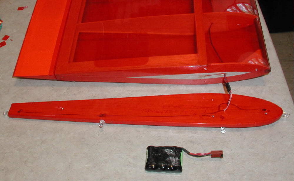
The photo above shows the wing tip plate complete & connected, ready to be mounted to the end of the wing with 4 screws. The battery shown is a 4 cell 300mAH NiMH battery which weighs 1.1 ounce, and wil light the whole setup for well over an hour. It is mounted inside the fuselage under the forward hatch on velcro, for easy access.
The X-BRITE green LEDs form KINGBRIGHT (Mouser part # 604-L7113VGC/H for $2.87 each ) are rated at 18,000mcd typical intensity. They have a forward voltage rating of 3.7 volts, however, which means that, on a 4 cell lighting battery supply, I need to wire them individually, with current limiting resistors to keep the current through each LED to the 20mA maximum. a 1.8 volt differential, divided by the .020Amp desired current figure, gives us a required resistance value of 90 Ohms. The next larger standard value is 91 Ohms- very close to the calculated value. A 47 Ohm 1/4 watt resistor is used to handle the current limiting to two of these LEDs, so using two 47 Ohm resistors, each limiting current to two of the four green LEDs , does the job nicely. (I measure 72.7mA total for the 4 LEDs- which gives plenty of intensity to the Green LEDs.
(The completed lighted wing tips actually each came out 1/4 ounce lighter than the 1/8" lite ply ones I took off.)
I also add two 10,000 mcd 'True Orange' LEDs to either side of the forward section of the fuselage at the bottom edges, and two of the 9,500 mcd Yellow Toshiba TLYE20T LEDs (Hosfelt part # 25-408 for $1.45 each) on either side of the fuselage bottom edges back under the leading edge of the horizontal stabilizer. (Since I did not install wiring for these when the fuselage was built, I'll tape them and their wireing in place on the belly of the fuselage.) These 4 on the lower edges of the fuselage will give good pitch attitude definition when settleing in to land, and will be directed out to the sides for maximum visibility. Two separate 75 Ohm resistors are used, to set up the current limiting on each pair of LEDs.
I used 'wire wrap wire' in a color to match the fuselage's covering to wire these fuselage LEDs, & because it's thin; this is a solid conductor insulated wire, which tapes in place easily with scotch clear multi-purpose tape. Once the wires from the LEDs were inside the fuselage, I added in the series resistors, and from there completed my wiring with a different flexible multi-stranded insulated wire for the lead going to the battery coupler, so it can flex while being connected & disconnected for a long time without problems.
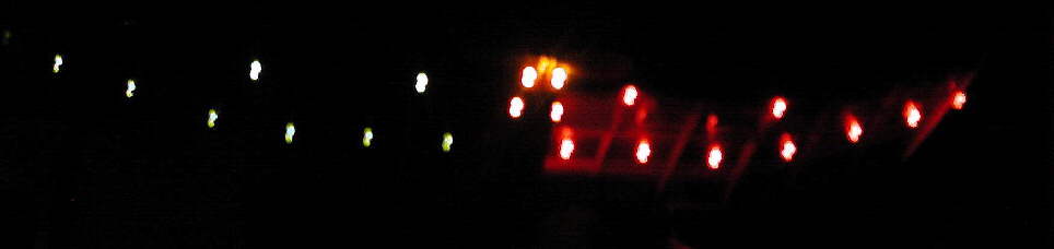
While there are fewer LEDs on the wing than I built into the FLOATMASTER II's wing I previously completed, I expect that four X-BRITE Leds on each wing tip should be very visible & flyable; these are really intense LEDs! The whole point, of course, is to have good enough visibility to allow you to maintain your sense of the airplane's orientation and attitude at all times, and be comfortable enough with your sense of continuous orientation to fly rolls, loops, or Hammerhead stalls, etc., if you wish. Yes, it does take a bit of time to get used to flying a pattern of lights around the sky, but not too long. I certainly enjoy it- I expect you might enjoy it too!
I like the visibility offered by mounting a couple of the LEDs on each wing pointing forward at the wing's leading edge, as well as having a couple of each color pointing back off the trailing edge (for visibility while the aircraft is flying straight away from you, especially on initial climb-out.) I also have one on the wing tip, pointing out the end, and three along the under side of the spar, pointing down. All LEDs are fairly directional, and they are quite visible when pointed right at you- nice for landing approaches... just try to set up your arrangement so that there is no orientation in which you loose sight of all of the LEDs at the same time- this is what we referr to as 'reinventing darkness', and is associated with a rather severe 'pucker factor' ... I think you know what I mean! {grin}
I've also set up aircraft with Yellow LEDs pointing forwards on the forward fuselage or at the center of the leading edge of the wing; this gives added definition when the aircraft is coming towards you.
NOTE: on my first test flight of a tape-on set of lights on my WATTSINNIT in July of 2001, in addition to the 4 yellow LEDs on the nose, I had also wired 4 more yellow LEDs along the aft fuselage belly. However, my radio receiver antenna was also routed near the light wiring. The result was a 'masking' of the radio antenna and greatly reduced radio range. If you do add more lights aft, and your radio receiver antenna is routed in the same area, you'll want to do a good range check with all systems operating before you commit your setup to the "wild dark yonder"!!!
The ground wire / return wire from the outboard set of 2 LEDs on a wing can also be used as the ground / return wire for the inboard sets of LEDs on that same wing. However, each set of 2 LED's needs it's own Positive Supply wire directly from the positive supply, after the in-line voltage droppinng diode or resistor. In other words, after the current limiting diode or resistor, my main supply wire splits out to each of the first LEDs in four sets.
NOTE: Mounting some of the LED's along the trailing edge of the wing might help greatly in improving the visibility- I highly recommend this!.
If your night flying location has "Light Pollution", it'll be more challenging getting your eyes to adjust to the night so you can see your aircraft really well. I now have a Brinkman LED flashlight (bought at Wall-Mart) supplied with three colored lens covers; I use it with the red cover in place to see what I'm doing when setting up a Night Flyer for flight, without adversely affecting my night vision.
For high speed & aorobatic wet powered models, the 1998 article below offers approaches for a lighting system giving good definition to a larger aircraft at greater distances; I've now flown the NITEOWL with it's night flight lighting system at maybe 1000 feet away or more at night. There's more detail on the NITEOWL page about the light installation built into this aircraft. With the newer 10,000 mcd LEDs available now, this type of setup should offer good visibility, too! (When in doubt, add more LEDs!)