

After having the BlueCor material on hand for almost a year, it was finally time to do something with it. Thanks to Rod Baron & Ron Teke of SPARCS for demonstrating just how well flat pate airfoil airplanes can fly; & thanks to Keith Brown for the neat CD-ROM type motor I ended up with at this year's SPARCS Christmas Party gift exchange...
I needed something on which to fly this impressive motor, and after seeing Rod's BlueCor planes flying so impressively earlier this year, and then seeing Ron's Red & Black BlueCor plane flying just Saturday morning (Dec. 18th) at Farmer's Korner, & then talking a bit more with Keith, I decided that it was time to finally get busy!
(Winter is building season for me- it's when I take a bit of time now & then to work on a project. So I thought I'd pass along a few details on how easy it can be to build one of these airplanes. If it gets some of you interested in building your own, then my time writing up these brief notes will be rewarded!
(There are no 'plans' as such- it doesn't really take any- but I did lay out cutting template paterns on poster board so that more parts can easily be marked. SPARCS Members can contact me if they are interested in building one of these airplanes after the flight testing is actually completed.The building process is very straight forward, and will be well illustrated in these photos & text. More photos will be added to this page after I complete the next stage; the ends of this page has the latest updates.)
Keith said that a 12 Ounce plane would have great performance with the 16 Ounce thrust motor,(& I certainly agreed!), so that was the target weight limit if possible. BlueCor fan fold panels are 23-1/2" between folds, and 50" wide, so length of the fuselage horizontal panel was dictated at the 23-1/2" length by the material. This is what should be considered as 'close-coupled'; a longer tail moment would result in a smoother flying aircraft... but hey, I'm the guy that enjoys flying the "Short Hare"... this layout is not as close-coupled as that plane, and I have a lot of fun flying it...! After doing a rough layout on graph paper, I started my final layout directly on the foam sheet. I cut the bevels on the aileron / wing joint in the main cutting session, and merely swapped the ailerons to the opposite sides to use them as they came out.
The result of my efforts it a total of about one day are in the photos I've attached.


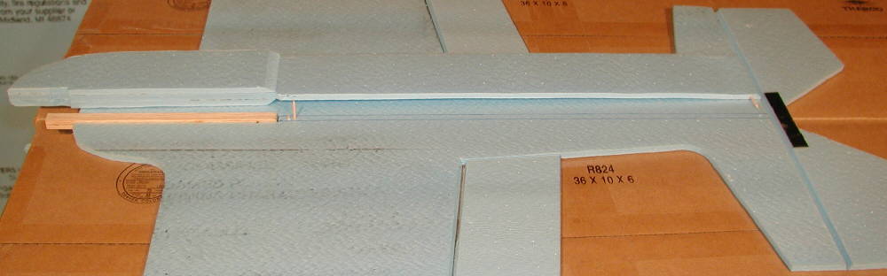
The entire wing, horizontal fuselage member, and horizontal stabilizer are kept together, cut in one continuous piece. The Vertical fuselage is longer by another 2-1/8", surrounding the motor. Fuselage finished length is 30" from the front of the prop mount to the trailing edge of the elevator.
Wingspan was designed at 30", with a single 1/8" diameter CF tube wing spar (which was installed in a slot made with a Dremel cutter bit in a Dremel Tool equiped with a router head setup. I installed it in the 1/8" deep slot with 5 minute epoxy.
The motor mount ( a 5/16" diameter dowel to insert into Keith's motor mount) was epoxied in place next. (I actually replaced the one in these first photos with a longer one that extends back farther through the core of the fuselage past the battery pack mounting area, to firmly transfer the motor thrust and the battery weight to the rest of the airframe.)


The top fuselage piece was then epoxied in place, (using one toothpick piece as a locating pin close to the tail to help alignment while the epoxy set up.)

The elevator was then tape-hinged to the horizontal stabilizer (after having the center section reinforced with some 1/2" wide .007" C.F. material.) I use Scotch multi-purpose transparent tape for hinging purposes, applying the top side tape first, then another layer from the underside second, so that the tape pieces join to each other in the middle of the hinge line.

The lower fuselage was epoxied in place next, again using a short toothpick piece as a locator pin at the tail end.
The rudder was next reinforced with CF material in the control horn area, then tape-hinged to the vertical stabilizer.

Finally, the Ailerons were tape-hinged to the wing.

I plan to glue the 1/32" birch plywood control horms into place in custom slots through the BlueCor foam. Ordorless CyA was used & worked well for this job. (Since I'm intolerant of solvents, but like quick setting time, the epoxy and the odorless CyA glue are my choice for building. I'm also using a bit of low temperature hot melt glue in certain areas; it's likely only suitable for places where you can work fast before the glue cools too much to bond well. I'll use 1/32" music wire for aileron control linkage ends, attached to the ends of .060" solid CF rods for all control rods.

Result?: Airframe is at about 3-7/8 Oz, before painting.
So this is the progress I made in less than one day, starting from scratch & laying it out before starting the cutting.
[Once the painting was completed it was 1/2 ounce heavier, ready for the control system installation.)
PAINTING
I tested some bright spray paints, and confirmed what others say; only certain products can be used on the BlueCor without damaging the material. I had a 3 Oz. can of PACTRA spray paint designed for painting polycarbonate bodies on RC cars; it did not attack the BlueCor's plastic surface film, but did bond well to it. (It does attack the core foam, however, so use it carefully & don't try to pain too 'wet' ; use mist coats with the spray can held at a distance, and let dry between coats.) I used this on the entire lower surface of the aircraft.
I used the inexpensive CERAMICOTE acrylic paints from WalMart's craft section in Purple and black to dress it up a bit on the upper portion; these colors were applied with a brush. The result isn't too hard to look at...! It's definitely highly visible from below when it's in the air!
I used three of the inexpensive Blue Bird .21 Oz servos, installed with low temperature hot melt glue.
I custom made 1/32" birch ply control horns, and glued them in place with odorless CyA glue.
I installed a .3 Oz. GWS 6 channel receiver, then mounted the 1-1/2 Oz motor, 1/4 Oz. Phoenix 10 ESC, & a prop. With a 3 cell Li-Ion 1200 mAH battery which weighs 4-1/8 Oz, the completed aircraft is ready to fly at 12-1/8 ounces. I used an APC 9x4.7 slowflyer prop for the first flights, then later switched to an 8x6 GWS slowflyer propeller; this motor performs well on this prop on 1 3 cell Lithium battery.
Flight tests were finally flown on Sunday, December 26th, 2004 in a small area just off the end of my driveway; this plane is flying great, and does not need a lot of area to fly. It is close-coupled enough to flat spin nicely; because of this ccharacteristic, it's definitely not a trainer! But it flies inverted nicely, rolls smoothly & loops tightly, and glides under reasonable control with the motor off, for predictable landings in a modest amount of space. (A flat plate wing is certainly not intended as any form of 'glider', but power off landings are essential on a no-landing-gear aircraft, so I'm very satisfied with the no-power maneuvering capabilities.
Note: 1-18-05: I'm now using a KOKAM 1500mAH LiPo battery to fly this aircraft; it's producing more RPM than than it did when using the surplus Li-Ion cells on which I first flew it.)
They say 'A picture is worth a thousand words", and since I type slowly & do not have time to write up a lot of the details right now, I'll simply offer the following photos.
QUICK NOTES:
Balance on a flat plate winged aircraft works well at about 29% to 30% of the wing chord. I had installed the C.F. tube spar at 30% of chord, and flying with the balance on the spar at the 30% location works well.
Receiver Antenna: this is taped on top of the wing, rather than draging out behind.
Battery Update 1-18-05: the location of the battery was the last item I dealt with, to finalize the balance. It is now held in place in it's cutout with a couple of clear plastic covers (made from salvaged packaging materials) which are taped in place on either side. One side is tape hinged, so that it can be swung open for battery placement / changing, and taped shut for flight.
LINKAGES: Note the 'safety pin' front ends on the control linkage rods; these are formed from 1/32" music wire, and installed on the ends of the C.F. rods with heat shrrink tubing. Once final trim alignment is adjusted with the radio trims centered, a drop of CyA glue locks these links to the rods. (The other end uses a short Z bend coupler, anso heat-shrink & glue mounted to the control rod.)


Parting notes: For a novice pilot, making a longer fuselage would smooth out the handling, but you would have to use a different layout, with a separate wing, and separate fuselage members, to extend the length. (Keep in mind the dimensions of the fan-fold sheet.) In the process, you would likely loose the flat-spin capability, and find a bit smoother handling.)

After installing the spar with ordorless (foam safe) CyA glue the 10mm square motor mount stick is glued in place; it extends back to the wing spar. The top surface of the motor mount stick is placed flush with the top surface of the wing section of BlueCor- it extends 1/8" below.
Once the vertical fuselage section is split lengthwise and trimmed out to match & clear the motor installation, the top piece is glued in place. Toothpick sections are used as 'locator pins' when gluing the top section in place; (match the trailing edges at the hinge lines for the elevator and rudder.) Once the 5 minute epoxy I used was set for a few minutes, I did a final fit on the ailerons and then tape-hinged them in place. The elevator was tape-hinged in place next. (Tape top first, then bottom after.)

Above is a closer view of the upper nose section; the motor stick was installed at an over-long length, then trimmed back to leave the motor recessed enough to be protected by the lower fuselage section once it is all together.
After fitting the lower fuselage section to the under-side of the horizontal wing section, I added 'doublers' on either side of the lower forward fuselage section, from the nose back to the wing spar area. This will make this area, which not only carries the flight battery, but also inevitably takes the most wear & tear on landings, much more durable. It also brings it out to a full 3/4" thick, so the 3 cell KOKAM 1500 LiPo battery I am using will fit within this thickness, and not protrude out the sides. I'll determine the battery location last as the final 'balancing act', and make a snug fitting cutout. For winter flying, a clear plastic cover will be permanently taped in place on one side, and another clear plastic battery compartment cover will be tape-hinged on the other side, and closed with tape to keep the battery in place.
(Protecting LiPo batteries form damage on landings is a high priority!) For warm weather flying, the solid cover panels may be modified to allow for battery cooling air flow; but for winter flying here in the central Colorado Rockies, keeping the battery warm enough to perform well is an important consideration.)
You can also see the toothpick 'locator pins' I installed which will index the lower fuselage section into it's exact desired position while the epoxy glue is setting.

Once the epoxy had set, I used a bit of low temperature hot melt glue to lightly reinforce the forward joining area. Then I did an overlay along the bottom forward edge with 1-1/2" wide cross-fiber nylon filament tape. 3/4" wide nylon filament tape is used on the aft lower fuselage bottom edge to add durability.

The photo above shows the BP21 motor installed, mounted on a trimmed down GWS motor mount (which is included with the BP21 motor.) You do have to figure out where to drill the lower two holes for mounting the motor to the mount, but it is a good fit, with the prop shaft center line just above the upper surface of the motor mount stick. I trimmed away as much excess plastic as possible; the results are shown in this photo.)
Long range light weight 4 Channel & 6 channel Receivers: (Berg 4L or CORONA 410 and 610 receivers are now used and recommended.)
UnitedHobbies.com offers GREAT prices on motor & ESC combos (- under $20 for the set!), servos, receivers, and LiPoly batteries; yes, it takes some time to receive a shipment from Hong Kong, but the values are great.
Another source for great motor prices is BlackdogRC.com in Wisconsin.

A more powerful 2409-18 brushless motor is used on this version of the Spinner. I'm flying a 3S1020 mAH battery pack in this SPINNER; (my older KOKAM 3S 1500 mAH packs are aging, and do not provide anywhere near the power / RPMs which the new United Hobbies 20C packs produce!
The counter-balanced tail improves elevator response, with less loads on the servo.
The added tape-on landing gear makes ground handling easy when flying from suitable areas ; takeoffs, landings, and touch-and-goes are possible. When building the fuselage, a epoxied a layer of 1/16" birch ply to the fuselage belly, then covered it with Scotch Cross-filament tape. The landing gear is simply taped in place to this plate with more of the cross-filament tape. A tail skid wire was also installed and taped in place.
This is a very smooth handling aircraft, with unlimited vertical performance!


[Originally Posted by viking60 on RCGroups in early June of 2007:]
[Andy was asking about adding layers with KF step on both top & bottom for symmetrical wing handling:]
I did this on the third prototype of my "SPINNER" design late last year - (an aerobatic design which flat spins superbly), with the added Bluecor panels on both top & bottom. I rounded the leading edge to a symmetrical contour, and ended the tripler panels at 30% of chord, so the balance point / CG would stay forward at that point. I used very light 1mm CF rod spars, simply glued to the wing's top & bottom surfaces just in front of the steps at 30% of chord.
It acts much more like a fully symmetrical wing than the flat plate wings could ever fly- very smooth and responsive, with NO flex, and NONE of the pitch-sensitivity that will invariably be seen with a thin flate plate wing.
So for aerobatic flying & 'symmetrical wing' handling, I highly recommend it.
On the Dancer design with the doubler planel on top of the wing extending back to 50% of chord, the ideal flying CG / balance point shifted back to 40% of chord. Lift is good, high speed performance is very good, wind penetration is very good, and the glide is impressive. By doing extensive shaping of the leading edge, trailing edge, and wing tips, the DANCER became a far more efficient glider that I had at first expected it could.
Contrary to what one might expect based on the old paradigm 'conventional wisdom', adding the Kline-Fogelman step to a wing, either on top or bottom, or both, may actually effectively REDUCE overall drag!
I'll recommend that everyone who's interested should read Dick Kline's book, "The Ultimate Paper Airplane" for more of the early story and a bit more of the technical aspects of how adding the KF step changes the pressure distributions of a wing in beneficial ways. The book was published about 20 years ago, so there's more to the story today that's not in the book, thanks to the ongoing work, prototyping, and information shareing of people on these forums.
Imagine if you can: a 'discontinuity' that actually REDUCES drag, substantially helps to minimize air separations from the wing surfaces, and actually will allow a wing to fly faster than it can without the addition of the KF step treatments..... you finally have to build & fly them to experience this for yourself! (The DANCER wings are the best flying examples of this to date.)
The fun continues.... some days it borders on pure magic!!!
VIKING
~~~~~~~~~~~~~~~~~~~~~~~~~~~~~~~~~~~~~
Friends,
I finally took some photos of the SPINNER I mentioned, and have added them [above]
As you can see in the photo below, the leading edge is well-rounded, and the added layers extend back only to the 30% of chord point, where the CG / balance is located for good flight performance.
With the steps on both top & bottom at 30% of chord, I do not see any added 'lift' or glide over the flat plate wing; but it is a rigid and very smooth flying wing which performs a lot like a fatter symmetrical aerobatic wing. As I mentioned above, there is no pitch sensitivity.
DANCER's wing was designed and built for a different performance task: to penetrate wind well, generate lift with minimum drag, and glide cleanly and efficiently. To accomplish this, the extra layer with the KF step extends back to 50% of chord. This places the ideal balance point for gliding performance on this wing at about 38% to 40% of chord . Please note; if the forward 1/3 of the wing's airfoil is not shaped, the wing can't generate the lift which it does on DANCER, and can not glide as cleanly / efficiently. The thinning and shaping of the trailing edges and wing tips further enhance the performance by minimizing drag. And finally, drooping both ailerons slightly [along with the minimal amount of positive wing incidence] allows the wing to perform consistently across a wide speed range, from hotliner flying with throttle wide open, to a slow floating glide, without trim changes.
Bottom Line: *IF* properly implemented, the Kline-Fogleman step treatment can enhance the performance of a wide variety of wings / airfoils. It can NOT make up for other design deficiencies, however...
The Fun Continues!
~~~~~~~~~~~~~~~~~~~~~~~~~~~~~~~~~~~~~~
[DRITCH Asked:] "So would the Spinner type wing be good for a dart?"
Nice Web Site.
[My Reply 06-14-2007:] DRITCH,
Thanks for the kind words!
There are a wide variety of Dart morphs / variants; with the low aspect ratio wing layout and really deep chord on the wings at the center, you may loose more with the extra weight than you will possibly gain in performance...
Reducing pitch sensitivity with a thicker leading edge may be useful, but if that's not an issue on a very light Dart, then keeping it simple & light may be of grerater value. (Shifting balance forward also reduces pitch sensitivity.)
My CURVACIOUS! II performs well without adding anything; it's a flat plate wing with a very deep center chord, very low aspect ratio (1:1?) and no dihedral...
Stiffening a flat plate wing for better handling can be done without adding an extra layer; I use the 1mm C.F. rods (from BPHobbies.com for .99 each in 1 meter lengths) to do this, as shown on the CURVACIOUS! II web page:
~~~~~~~~~~~~~~~~~
ZIO asked: "Those KF airfoils look like rectangles to me...could someone show me what a KF should look like if the wing were sliced down the chord? Like if I were to make a balsa wing, how would the rib look like? I know there is a step involved but those two planes have completely threw my idea off. I thought it was shaped like a normal airfoil then just stoped."
Good question; the Kline-Fogleman step is more easily thought of as an 'Airfoil Treatment', [the concept of a 'discontinuity' that does not have to produce a drag penalty when properly implemented]- rather than as a specific airfoil, per se.... When you look at the wide variety of what's being done & called KF 'modifications' or 'variants', this becomes more appearant.
The DANCER is an example of a higher aspect wing design which is done in FFF, and which is built out in a 7.5% thick wing with the overall airfoil profile very similar to an RG14; it's an example of how the KF step treatment can be effectively implemented to achieve very good performance, while working with FFF material.
Aircraft / wing design & performance evaluation is always relative to the desired performance task / envelope; for some designs, simply adding a step / discontinuity may not in itself improve performance observably... Incorporating an EFFECTIVE discontinuity / step in the optimum placement on a wing, with the optimum depth, relative to the desired performance envelope, is where the 'magic' of aerodynamic design comes in to play.
If the step is too deep, it becomes a 'drag pocket'; this might be desired in some designs, but will hurt performance on many others. (Adding a deep step to the underside of an undercambered wing is a good example of how to observe a severe drag penalty...)
Dancer's 9% thick wing was the demonstration of the implementation of a dual step wing to eliminate the 'drag pocket' penalty; visit the Slim BEAGLE / DANCER web page for the airfoil diagram and a lot more of the details.
(There are a lot of experiments that have been done that have not shown performance improvments, too... even the NASA engineers, in their testing, didn't properly implement the KF step to be able to see it's potentials.....)
Since this thread started by asking about aerobatic pereformance, SPINNER 3 was offered as an example of an aircraft in a different (aerobatic) performance task envelope that implements a symmetrically stepped wing that does not suffer from observable "drag penalties" by having these discontinuities built into the wing at 30% of chord. It doesn't necessarily 'glide better' with power off, since it's a heavier aircraft with a higher wing loading.... But the wing's effective airfoil profile performs as intended.
The web page on the Dancer, (as linked above), will possibly help understand some of this better; things get burried deeply in the long discussion threads on RCGroups- that's the nature of a wide-open discussion forum.
Whatever you do, have fun doing it!!
VIKING
More later!!