Friends,
I first built a KF variant stepped FFF wing, implemented as a dual layer on my HOOT with this second layer added on top of the deep flat plate wing, extending back only to the CG point at approximately 25% of chord. With the two layer thicker leading edge and stiffer wing, it handled very smoothly and predictably...
When I buily the MANTAs, I initially flew the first one as a flat plate wing. Later I built the second MANTA, and I added the front doubler panels to both top and bottom... but again they extend back to only about 25% of chord. With the nicely rounded triple thickness leading edge, the wing was less pitch sensitive, and had almost no flex, so it flew very nicely.
On the third SPINNER which I designed & built, I wanted the thicker leading edge and stiffness produced by the triple layer forward section. Since balance / CG is at 30% of chord, I extended the tripler layers to that 30% of chord, with an evenly rounded symmetrical leading edge. It flew superbly- far smoother and more predictable, with far less wing flex than the two previous SPINNERS with their flat plate wings. With the thick leading edge, there is no pitch sensitivity. It's a great aerobatic aircraft- by far the best performing of the three SPINNERS (-all of which are still flying.)
With these three designs in the air, I started looking into what others were commenting about using the the Kline-Fogelman step treatment on their RC designs. One of the discussions which caught my attention and interest was Doug Montgomery's fledgling KFm5 DLG design. I was looking for a way to get a clean, efficient glide while building a relatively uncomplicated wing with sheet Bluecor material. What was most significant to me, conceptually, was that if the step was placed on the top surface back at 50% of chord, that a lightly loaded wing could glide quite efficiently.
Heat forming and shaping the wing's leading edge & overall airfoil countours similar to an RG14 airfoil, and tapering the trailing edge down to ~1/16" thickness, as well as implementing my heat-contoured upswept wing tip sections did a lot to clean up the aerodynamics.... but the really sweet concept was that, contrary to 'conventional wisdom', having the substantial 'discontinuity' of the 90 degree step at the rear edge of the top panel did not impose the drag penalty that most have been lead to believe would be observed. In fact, a *REDUCTION* in drag may actually be the result, according to some.
I decided to get the new Kline-Fogleman variant airfoiled wing flying quickly, so I worked over a fuselage / tailgroup which I already had on hand in order to do the test flying. (I have several other single layer undercambered Bluecor wings already built to fly comparisons on this same airframe, so this seemed a good approach to get into the test flying and comparisons quickly.)
This fuselage may look a bit familiar to some of you; it's one of my Blue Beagle variants, with a longer tail boom and larger tailgroup menbers. It's been flying since early last July, but it went through a bit of upgrades earlier today.
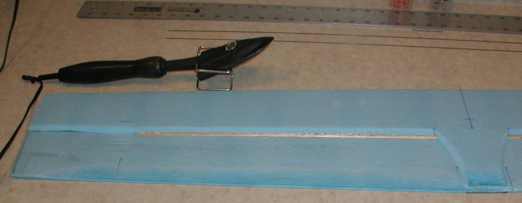
I used the heat-forming technique (using the covering iron) to heat-compress and thin all edges on the bluecor tailgroup menbers to minimize drag. Then I set the iron's heat setting lower (after testing on some scrap to find the right temperature) and did the heat-forming on the AquaRider foam fuselage, too. The nose and the rear edge were thinned substantially to make the fuselage more aerodynamicly efficient.
An E-Sky 8 gram servo was set into the center of the wing just in front of the spars (which are at 33 % of chord) with the outshaft on the underside of the wing. I cut away enough foam in the wing mounting area to clear the servo / arm / linkage. DuBro Mini EZ connectors are used on the 1/32" birch ply aileron horns, so that slight changes in aileron camber can be easily tested.
The motor is a 21 wind GBv kit motor, Y winding termination, driven by a CC Thunderbird 9 ESC, running on a 2S Li-Ion 1250 mAH pack, turning an 8x6 GWS prop.
Flying weight is at 10-1/4 ounces, Wing projected area is 2.2 square feet, resulting in a wing loading of 4.66 ounces per square foot.
I had only about a half hour of failing light at the end of the day to get in a bit of preliminary test flying, with cold air and mild turbulence. (I have the aileron channel mixing back into the rudder at a 10% mix.) Handling is very smooth, across the spectrum from under full power in climb, to low power cruising to maintain altitude, to glide. The upswept wing tips are definitely providing the dihedral-like stabilizing effects on this wing; in smoother air, it'll be able to be flown hands-off a fair amount of the time.
Rudder alone still has very good authority with this wing planform. It's also fun to flatten out rudder turns by applying oposite aileron. I think this is going to be a fun wing to fly a lot more!!
Conditions late in the evening, just after a brief session of snow flurries, were not appropriate to do much evaluation of the power-off glide characteristics- that will have to await a more favorable flying day!
I'd really enjoy getting this wing on a light weight HLG fuselage, to see how it performs at an even lighter wing loading; but for now, I can swap wings around on this airframe, to do some of the comparisons between the K-F variant wing and the various undercambered single thickness wings which I already have on hand. I'll report my evaluation results.
(Further information on the heat-forming techniques are included in the SOARBIRD discussion thread on RCGroups, and in the KFm-5 DLG discussion thread.)

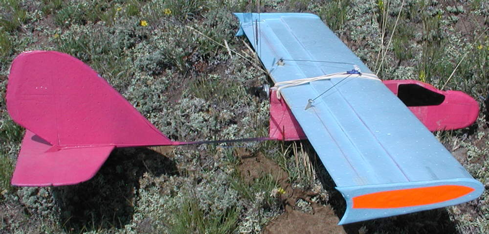
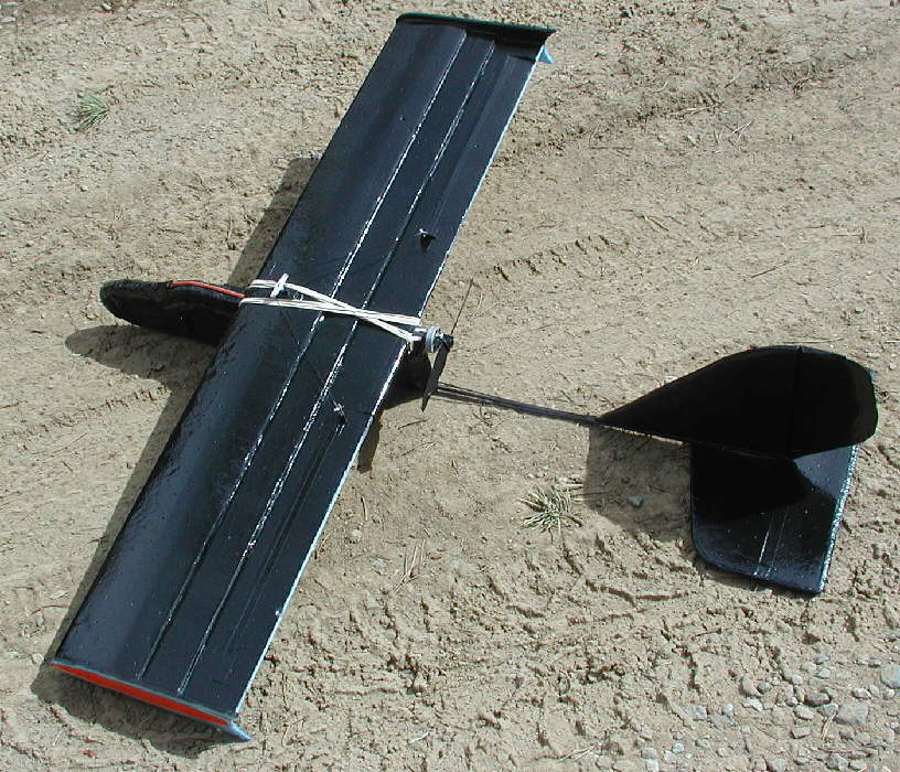
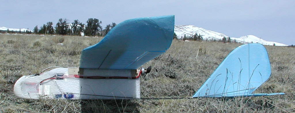
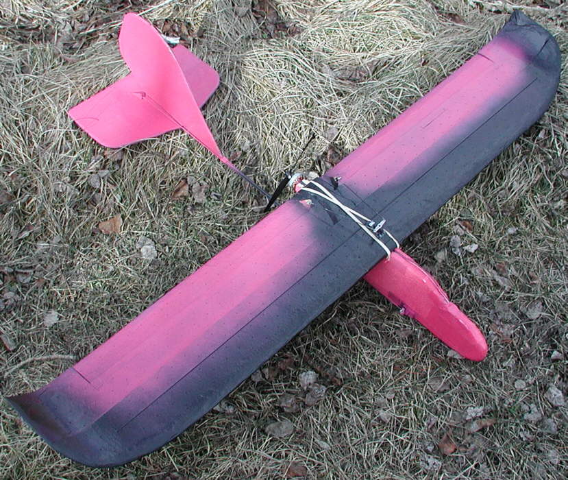
[Above]: New 46" span, 7" chord aileron wing with Kline-Fogleman airfoil being flown on an AquaRider fuselage BEAGLE.

[Above]: Left side, showing most of the gear; wing uses 2-1/8" up upsweep starting just beyond the center 39-3/4" long spar structure.
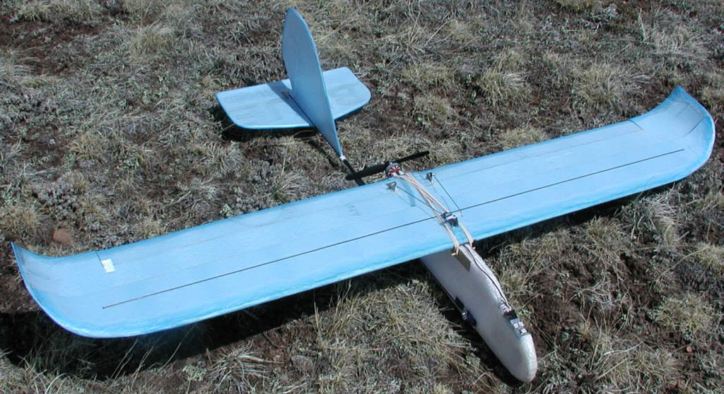
[Above]: Right Side

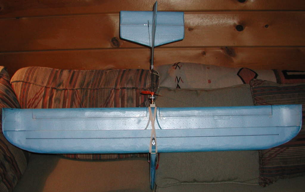
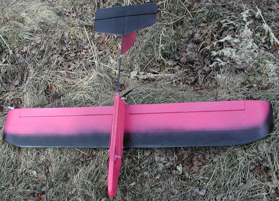
[Above]: Top side; Step is at 50% of chord, maximum thickness is 7.44% of chord, while spars are at 33% of chord. This wing is flying great with the balance at 40% of chord.

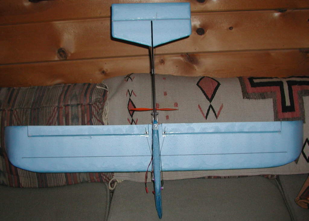
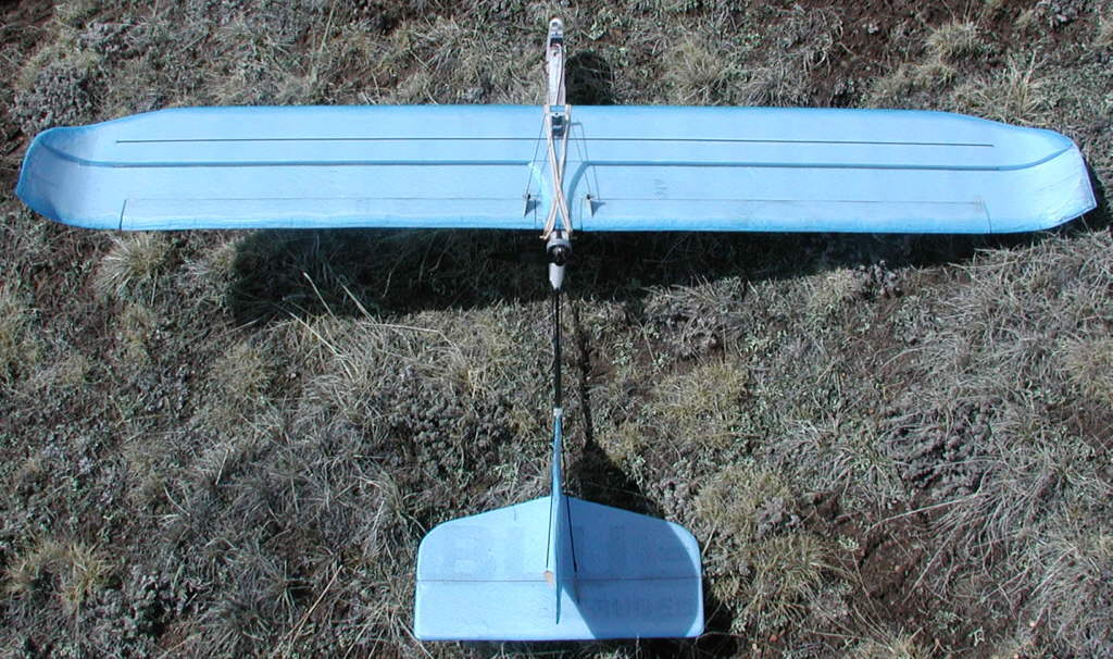
[Above]: Underside, showing aileron linkage; ailerons are 1-9/16" deep. 17-13/16" span each; wing spars are 1mm CF rod 1 meter long.

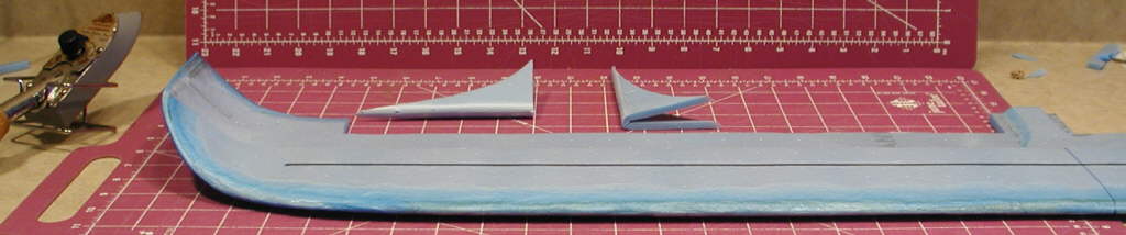
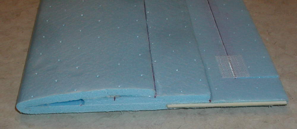
[Above]: Extensive heat forming of Bluecor can be done with a covering iron. This 46" span Glider wing with a Kline Fogleman modified airfoil started as a folded section of Bluecor, Then was shaped from there.

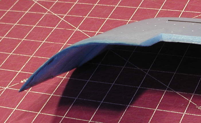
[Above]: Here's the trailing edge of the upswept wing tip, clearly ilustration how much foam re-compression and strengthening can be achieved with the technique. <1/16" thick trailing edges now, very strong, without any added weight

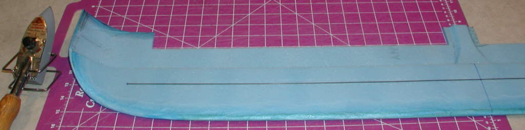
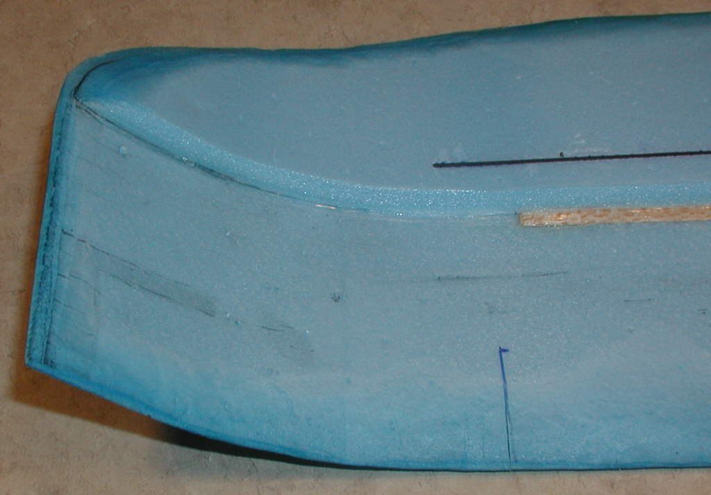
[Above]: This wing is just over 6% thick at the top step; the leading edge has been reshaped into a better airfoil by heat compressing the foam along the entire leading edge; center line of L.E is now at ~25% of total thickness.
I've discovered that a covering iron, set to just the right temperature, can be used to shape, compress, and heat-temper the Bluecor material. The result is a smooth transition into fairly thin trailing edges and leading edges without sanding away any of the material; instead, the foam is compressed & heat-condensed and tempered into a much firmer composition in the treated areas. the photos below show the results.
Being able to produce thin, strong leading and trailing edges on Bluecor aircraft parts using this new heat-forming technique shows great promise! I'm rather excited about the possibilities, to say the least. I've never heard / read of anyone using this technique before. I know I'll be using it on many designs from now on!
The first detail is to determine the right temperature setting for your covering iron. (I'm using an older iron with a flat bottom & fairly sharp edges to do the detail work on the aileron 'feather' contours, and it's working well for that.)
Experimenting and practicing on scrap will help find the correct temperature setting. (Somewhere burried in one of my cabinets / drawers, I may still have a temperature gauge for covering irons; if I can excavate that, I'll be able to post an actual temperature reading of the setting I'm using.)
I'll say this for now: the setting I'm using is well above what I'd use to attach Ultracoat / Oracover to a built-up structure; on this iron, the 2 setting is at 12 o'clock; while I'd use a setting of from 1.8 to 1.9 on the covering materials, I'm using a setting of close to 2.2 with this new Bluecor shaping technique.
If the iron is set too hot, then you can't control the effect- the surface of the material melts excessively before the heat penetrates the core; too cool, and the foam doesn't respond / compress / fuse properly. A bit of patience is needed to allow the heat to penetrate the core, for the iron to do it's job- it's fairly fast, but does take a bit of time to achieve a finished shape. Finding the right temperature setting is then a critical factor.
The next detail deals with technique; you need to press, rather than 'drag' or try to slide the iron on the foam to keep from distorting the shape. I find myself 'patting' the foam areas to achieve final finish shape; (continuous application of the iron is *not* the way to do it!
Just playing with some scrap to see how it handles will allow you to get the feel of it.
This technique is producing very nicely contoured / thinned / compressed / tempered / strengthened leading and trailing edges, which will minimize drag while increasing rigidness and durability of the Bluecor's edges.
I'm still working with the double faced Bluecor PP; I managed to squirrel away a good supply while it was still available locally. I don't have any of the pink or green that some are writing about using, so I can't comment on how this heat-forming technique works on those materials, but I'm expecting that a temperature setting can be found that will allow those materials to be worked with this technique, too.
I'll check the older BPHobbies 6mm Depron-like material I have on hand to see how it responds; my impression is that the core foam in that material seems to have less structural strength than the Bluecop PP....
[Update:] I checked the temperature at which I'm running my covering iron to do the Bluecor edge shaping; my Coverite 'Pocket Thermometer' is reading about 345 degrees F when placed in the center of the iron's lower surface.
[Update, posted April 6th to the KFm DLG discussion thread;] (Another menber commented): "Very interesting. The foam forming must take quite a bit of practice/patience. Good thing Bluecor is cheap Keep the pics and build info coming."
[BKS Response]: Actually, there was very little 'practice' involved; just a bit of playing around with a couple of pieces of scrap to get the temperature setting right. Then I just dove into thinning the edges of the tailgroup & ailerons for Soarbird III.
This KF variant wing was only my second project applying the heat-forming technique. PATIENCE is involved, mainly because heat doesn't penetrate into the core of Bluecor instantly. So you have to work progressively to end up with the results shown in the photos. I probably spent close to an hour doing all of the shaping on this entire wing once the spar structures were completed.
For the quickie builders who take pride in having a plane in the air flying in an hour from the time they start cutting foam, it would take a major mindset shift to invest this much time.... but for those who are looking to start with material like Bluecor, and end up with a more efficient glider wing, the time invested may show rewarding results.
I wanted to give the Kline-Fogleman airfoil concept a fair test, so cleaning up the rest of the aerodynamics as much as possible was a priority for me on this project. I still have several light, efficient built-up HLGs hanging on the ceiling with which to compare the flight characteristics of this new wing, so I'll be able to satisfy my own curiosity by the time I'm through putting this wing through it's paces.
I'll certainly report on the progress and flight testing results!
Gene B Asked: "Could you tell if this wing was able to 'hang in there' as slow as you other 8% underchambered wing? I assume the high speed was higher, with lower drag, but weight is up a tad as well..."
[BKS Reply, 4-8-2007:] More on the Kline-Fogleman Bluecor wing for the BEAGLES
Gene,
That's something I'll try to evaluate; flying conditions were marginal, so I did not have a chance to do the comparison yet. The ~42" span 7" chord undercambered wing is going to be hard to beat in gliding- especialy when we're carrying the weight of the motor and 120 gram battery pack...
But the KF wing promises to penetrate gusty / high winds easier, and handle high speeds and high power climbs smoothly without the 'ballooning' which undercambered wings can exhibit... so it may be a very good trade. But we still want the glide efficiency, too, so finding the 'magic' proportions & layout of a K-F variant wing which will offer the best performance in that category is the ultimate goal. This is the first experimental wing, and it's showing great promise- the layout parameters are very usable.
I'm curious as to what effect could be noticed by increasing the wing thickness another 1/16" = to 8.6% thickness on a 7" chord. (This could be done by using a 1/8" thich balsa strip at the step for the center 39-3/4" section.
The upswept wingtips are already showing very good handling characteristics which a flat wing would not have. It's relatively easy to roll up the tips once the spar structure is completed, and to then heat-temper the upswept tips so they'll hold their shape (with careful use of a heat gun) before hot-melt glueing the two layers together in the final shape. (I'm already liking the results that heat-shaping the edges with the covering iron is producing!)
[Posted to the 'Kline-Fogleman Flying Wing' discussion thread on April 8th, 2007:] With the top step at 50% of chord on a 7" chord wing, and the thickness at 7.44% of chord [1/16" balsa spacer added between two layers of Bluecor at the step] this wing is VERY stable with the balance at 40% of chord, and could be set up to be more responsive by simply shifting the balance back a bit more- possibly to 43% to 45% of chord - (IF there's adequate tailgroup area or a long enough tail boom / tail moment.)
Note: I did the first launch with added lead taped on the nose temporarily to bring the balance forward to 33% of chord, and it definitely flew nose-heavy; so I brought it in for a hand-catch, removed the lead to take balance back to 40% of chord, and relaunched; it's handling better there, but could still be more efficient and responsive if the balance were back a bit further. Considering that the 'high point' [KF top step] of this wing is back at 50% of chord, best glide efficviency may be back closer to 45%. I'll be exploring this soon. (I'll install the C.F rod spars back at 40% of chord on the next wing, anyway...)
WINGNUTT commented on 4-9-2007:
"I have really become a fan of the addition of a slope behind the step. My current test design uses a step peak at 40% chord which slopes back to the wing surface at 50% chord. With a step height of 7.5% thickness (measured from peak of step to other wing surface) this yields a slope angle of about 60 degrees. From what I can see, all of the KF properties are still held, but with reduced drag. I guess this is no longer a KF as there is no longer a hard step. Another great benefit is that in most cases, a spar is no longer required if the step is left hollow as it creates somewhat of a ‘D-box’ leading edge."
[BKS Reply]: Wingnutt,
Thanks for this report. Reduced drag is GOOD!! - Especially when we're speaking of gliding performance on HLGs & DLGs. (The Beagles really love to thermal, too!)
I should be able to quickly & easily add a sloping filler piece behind my step to test - (although the step is back at 50% on this wing for now) - just tape it in place & fly. I'll post a report when I do get a chance to test-fly my wing without, & then with it.
[CLICK HERE to jump to this dicuussion thread on RCGroups]
[Posted 4-11-2007 to the RCGroups Beagle discussion thread:] BEAGLE MORPHING: the next test prototype
Friends,
The new Kline-Fogleman variant wing is very promising, but weather here in the high rockies has not been suitable for further test flying... while some of the rest of the country is into a different version of spring, we're getting substantial snow, and winds are running into the 'small dog warning' category. (It must still be 'building season...)
I'm designing a new, sleeker pusher-powered fuselage for this new wing design, drawing upon what's already proven to work from the previous Beagle variants; so I'm scheming on putting a Beagle fuselage on a 'diet' - reducing the height of the body / fuselage from the present ~6" maximum, down to a maximum height of about 3.5" of Aquarider (or EPP) foam to reduce both drag and weight.
This depth of fuselage would still allow swinging up to a 6" prop, such as the GWS 6x3 DD prop. A GBv kit motor wound with 10 wraps of 24 Gauge wire [Y], running on a light weight 2S LiPoly pack can produce over 12.5 ounces of thrust at a current draw of 6.2 Amps with this prop. Prop pitch speed is around 35 MPH, good for this design. (The data on the 5" props did not look as good to me, so I'm designing this one to stay with the 6" props.)
So the light weight and inexpensive CSRC 2S 800mAH budget packs which I have on hand should perform fine in this trimmed-down BEAGLE variant, with a substantial weight reduction from the 2S 1300 packs my other Beagles are flying now.
I've cut the foam nose extra-long, and installed 24" of .157 diameter C.F. tail boom tube into the lower surface of the foam, with 10" in the foam, 14" extending back to the tailgroup / elevator hinge line.
The 3mm Depron for the lighter tail group is being shipped my way now; once it's here, I'll build out the light weight tail group, install the rest of the gear, determine where the battery needs to be for proper balance, & remove the excess foam from the nose and heat-form it into an aerodynamic profile. (The classic BEAGLE silhouette may suffer a bit from this trimming down, but the result should glide more efficiently, and be VERY aerobatic, too, while still retaining a reasonable amount of stability.
I'll post photos, detais, and hand-drawn plans as soon as the test flights are complete.
Posted 4-13-2007 to the Beagle discussion thread:
I had a chance to fly the first KFv flat-built aileron wing yesterday a bit on the BEAGLE in strange light conditions, but less winds... (flying between snow squalls!) So far, I'll report that it does not handle as easily in tight maneuvers & in slow high angle banking turns without flkying both rudder and ailerons - (there's simply not enough dihedral offered by the short upswept tips)- and it simply is not designed to handle the higher-alpha attitudes like a good 8% / 35% undercambered wing.
It definitely is able to penetrate high winds FAR better - (being a low camber airfoil), and can handle high speeds smoothly, but maneuvering well at low speeds does require smarter thumbs, flying rudder as well as ailerons. The way I built it, this first wing would make a superb slope flying wing. The wing loading might be bit high on this BEAGLE fuselage ; it may perform better when I get the trimmed-down / lightened version fuselage completed. (EDIT: It might also be an issue with the higher profile, and the higher wing incidence angle relative to the tailgroup.)
The rudder is definitely very useful and needed with this low-dihedral wing for clean flying, so it's not the best wing planform for a HLG (or any other design) built without a rudder, and it's not yet evolved into the "best" wing design for a novice. ;)
But it does nice rolls and flies inverted well, so there are some positives in the trade-off. This IS only the first prototype, after all, test flown on a different Beagle fuselage...
Thoughts on variations: Adding a 3mm depron panel to the undersurface back to 40% of chord might be the trick to increasing the low speed maneuverability & softening the stall characteristics. The other trick might be to reduce the span of the center flat section to ~70% of the span, and build in more polyhedral (or eliptical up-sweep) in the wing tip sections to increase the tight-area handling authority, if that type of flying is desired rather than smoother gliding performance.
Adding in the swept-back filler behind the top step, as Wingnutt speaks of, should also reduce drag and thereby improve the airfoil's glide. And thickening the spacer under the top step from it's present 1/16" thickness to 3/32" (or 1/8"?) thickness would effectively raise the effective 'camber line' of the airfoil a bit higher, which should increase lift. (By also adding in the swept-back filler behind this taller top step, there should not be the 'drag penalty' that would result without the filler...)
All of these various design aspects may be implemented on the next prototype wing, while keeping the building techniques as straight-forward as possible.
Friends,
I completed the new "SLIM BEAGLE" earlier today, and got it out as the winds were building to 12 to 15 MPH for the first flights. Flying weight is now at 8-7/8 ounces, flying the Kline-Fogleman variant wing, with a 2S 800 mAH battery in the nose. There's still a minimum of 1" of EPP foam around the front of the battery compartment to protect it during rough ground landings. (Further slimming and streamlining could possibly be done... but today, it was TIME TO FLY!!! And Oh, Boy- does this puppy FLY!!!
The Bluecor wing could be thought of as being somewhat / roughly comparable to an RG-14 wing, as far as thickness & camber. I find it flies very nicely when both ailerons are drooped about 3/32" from the bottom.
This downward reflex just in front of the trailing edge is somewhat similar to the RG 14 & 15, and the SD6000 series slope glider airfoils.
I moved the Aileron servo, linkages, & control horns to have the linkage on the top side of the wing, and kicked up the total travel on the ailerons while I was at it... and the results have me GRINNING for sure! Roll rate is now Very Satisfying!!!
Please understand: this KF variant airfoil is not really a slow speed airfoil, although it slows down nicely for hand-catches; and it would NOT be suitable for indoor flying... it likes to cover ground and cruise, both under power or in the glide. (If you slow it down too much and start to 'mush' it, it simply drops out of it's ideal performance envelope. When flown within that performance envelope, it's SWEET!!!
The 6x3 prop on the 10 turn [y] GBv kit motor allows this bird to climb like the proverbial homesick angel; it can be flown like a light weight hotliner to a certain extent. Speed is excellent; when the Beagle with the undercambered wing was tossed into the air today after flying 'SLIM', there was no comparison; winds were too strong for the Beagle, and it was quickly appearant that it was time to get him down again! In contrast, SLIM could climb out strongly and smoothly- no buffeting noticed at all, and the pitch attitude was very smooth and controllable.
The wing saddle on this puppy is set at about 1-1/4 degrees positive, relative to the tailboom and tailgroup; the motor incidence is set at zero, relative to the wing saddle. This results in a very neutral power on / power off attitude.
When floating low & slow just above ground level at close to stall, if full throttle is applied quickly, SLIM will dip his nose a bit as he quickly gets moving out to climb back up to altitude again. (I've seen a lot of E-powered gliders that handled a LOT worse when full power was applied to a aircraft at close to stall speed; but there's much better mannered handling with this SLIM puppy!
Yes, designs do get morphed - sometimes dramatically... (look at the 'Smart Dart' discussion thread for a recent example of morphing...!) This puppy really doesn't look much like a Beagle at this stage, and he certainly doesn't fly much like the ~30+ Beagles I've helped people build over the last couple of years... And I'm REALLY enjoying the present result of the ongoing 'morphing' process!

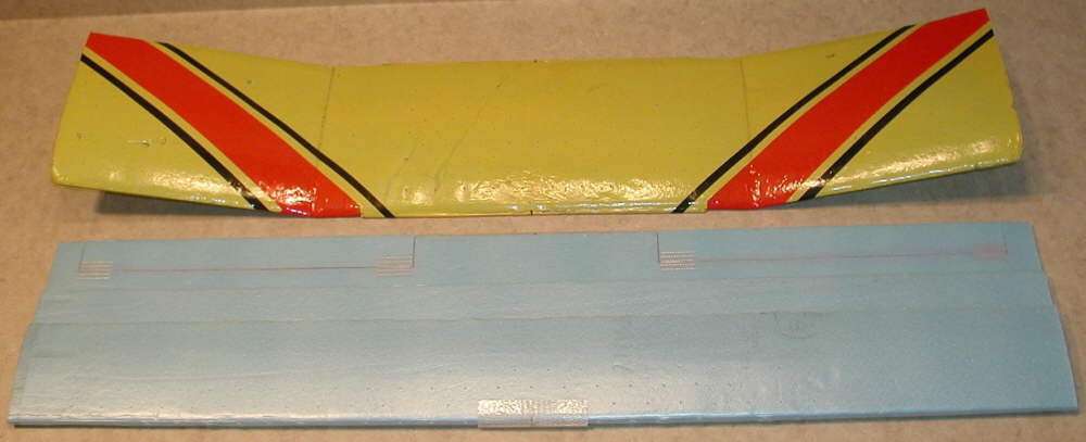
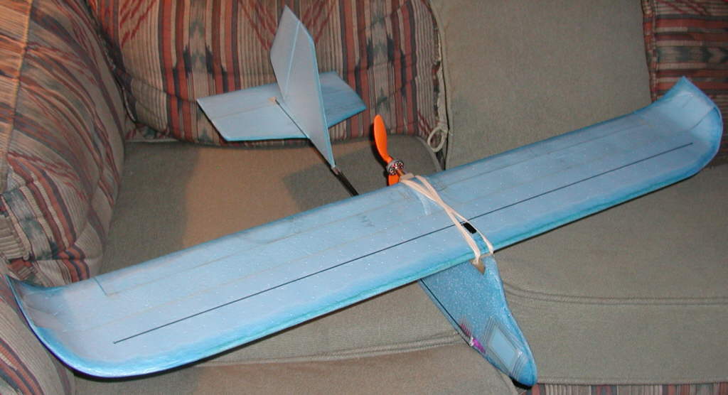
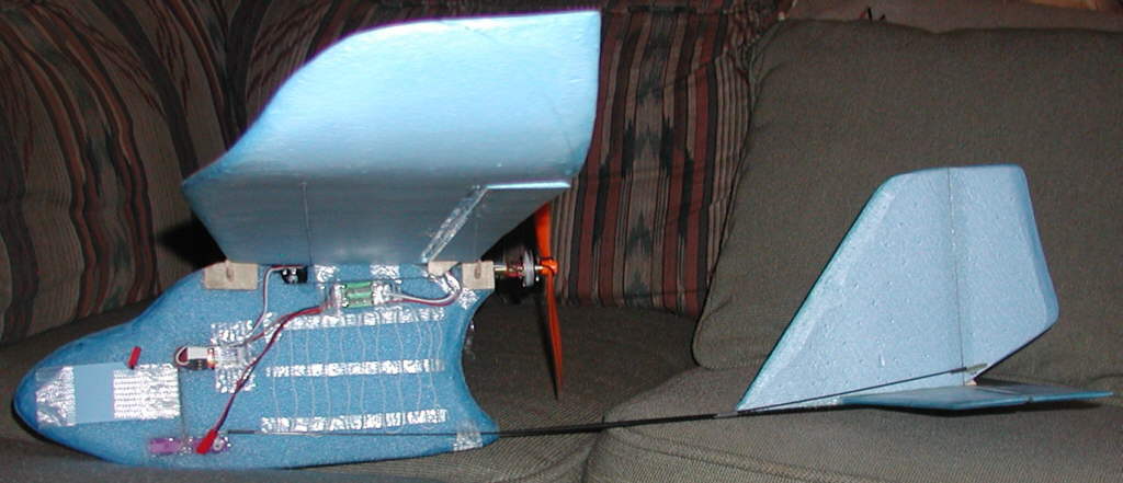
[Above]: EPP "SLIM Beagle" foam fuselage is 3-3/4" max height, 3/4" thick; balancing nicely with a 2S 800 mAH CSRC Budget pack. Flying weight 8-7/8 ounces.

[Above]:This Slim Beagle flies more like a hotliner under power- good rolls, inverted, & inside & outside loops. Handles winds MUCH better than the undercambered wings, and glides fairly well, too!

[Above]:KFv wing is 46" projected span after shaping upswept tips (starting with 47-1/2" foam.) Chord is 7". Single aileron servo used- working well.

[Above]:This fuselage can fly 7" or 7-1/2" chord wings by simply moving the front peg. Rx is on top of nose- easy access to plug in aileron servo lead when mounting wing

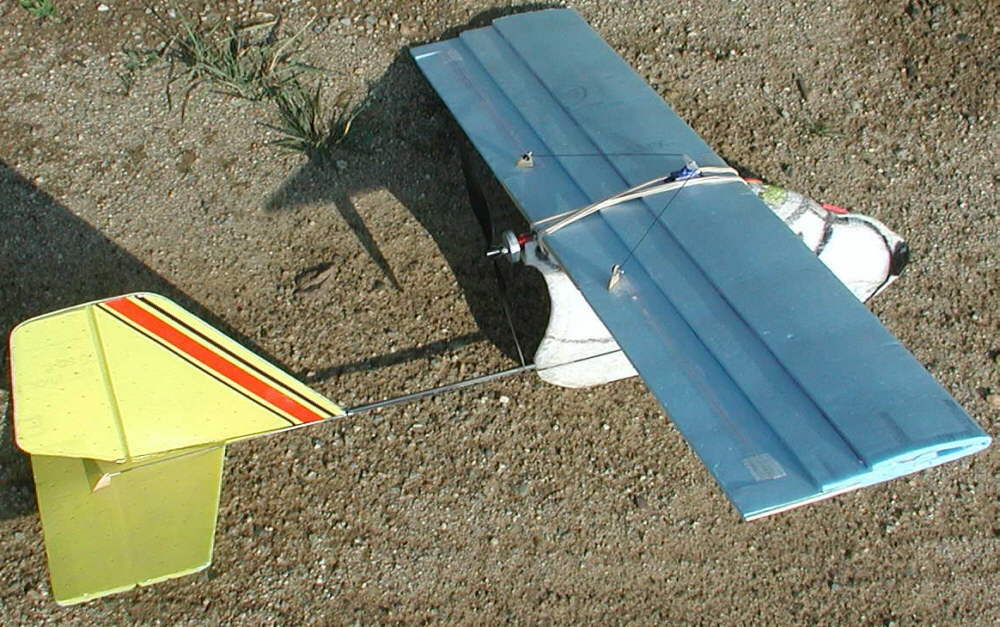
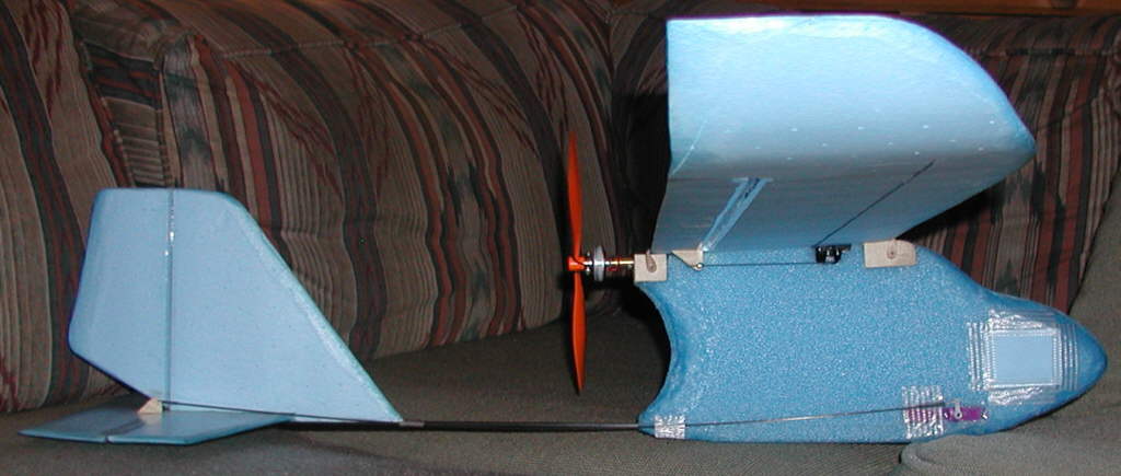
[Above]: On the left, the new "SLIM Beagle", flying 6x3 prop; on right, taller fuselage version flying 8x6 prop, undercambered wing
Friends,
Slimming down / reducing the height of a Beagle's fuselage for less drag is related to the motor you are going to run on it, and relates directly to prop size. I'm staying with 2S battery packs to minimize weight; if you do that, too, that means you will be looking for a higher Kv motor.
If you're not into winding your own motors, then a posible option that's readilly available is the GWS (2805-15?) - [the lightest of the three small GWS brushless motors.] It performs well swinging a 7x4 prop.
That would have you laying out your slimmed-down Beagle so you have clearance for that size prop- at least 3-5/8" of space from the center of the prop shaft down to the tail boom. So you could make a foam fuselage out of a piece that's a maximum height of about 4" to 4-1/8" (depending upon how much positive wing incidence you want to build into your wing mounting.)
I have a foam fuselage on the new SLIM BEAGLE that's 15-1/4" long overall at this time; that gives 1" of foam in front of the front end of the battery for protection, and about 3/4" of foam below the lowewr front corner of that battery. (I started with a longer blank until I could determine the battery location required to properly balance the new KFv wing, then carved away the excess.)
By insetting the radio receiver lower into the foam than I did at first, this puppy's nose could be slimmed down a bit more; but contouring and streamlining may be enough for my purposes on this one- it's not designed to fly over about 40MPH. If I were building another 90 MPH sloper, I'g focus more on streamlining for those airspeeds! (I already rounded the front profile smoothly, thinning the sides of the nose, as well as extensively thinning the foam fuselage's trailing edge just in front of the prop- a key area for reducing drag and smoothing airflow to the prop. )
The fun continues- more soon!!!
{Posted April 18th, 2007:]
Friends,
I did a quick application of visibility on my 46" span "Slim Beagle" Lite Hotliner today- Fuscia and Black are the primary colors!
It'll definitely show up against blue sky or clouds now!!
The paint added about 1/2 ounce to the flying weight... ah, tradeoffs... !!!
This design needs a designation, to keep the confusion to the minimum. I'm still referreing to it as the "SLIM BEAGLE" LITE HOTLINER .
[Ahhhh, but pink?)
HEY- it's a hotliner- it NEEDED hot colors!!
Note : Winds were up to 33.7 MPH on the wind meter at Kenosha Pass just after 3PM today when I finally got there, so this lite bird stayed in the vehicle, while I flew my Predatorized BEE for a while... another day!

[Above]: This "Slim Beagle" Lite Hotliner now has enough color for visibility in the air!

[Above]: Black shows up well against the sky from below- especially as you begin to 'speck out' in a good thermal. the Fuscia is very visible down low, allowing irreverent hotliner-style aerobatics.
Added 4-23-2007
Friends,
I got in some GREAT flying with the new 'Slim Beagle' with it's Kline-Fogleman variant wing yesterday. It is riding light thermal lift *very* efficiently. At 46" span and 7" chord, it was up to the visibility limits, 'specked out' many times, and had to be flown back down out of the lift.
A fter flying the thermal lift for the morning, we moved to do some slope flying on the South facing side of Kenosha Pass, since the light winds were out of the south.
(A Flying Buddy had a recently completed a lightweight Wild Wing that he wanted to test in the slope lift.) The lift was light and cyclic when we starterd flying, and the Wild Wing, at 10-3/4 ounces flying weight, could not stay up for very long at a time when the wind / lift cycles died. But the new Slim Beagle, with the KF variant wing, could stay up far more easily, and flew the light slope lift well.
About every 4 or 5 minutes, a wave of stronger lift and winds would cycle through the area, and at times later in the flying session, the winds would be peaking close to 20 MPH. Although the wing loading is only 4 Ounces per square foot, the new KFv wing on the Slim Beagle could penetrate these stronger winds well when the trim was kicked forward for a more nose-down attitude, working back & forth across the slope at substantially higher speeds. The wing is stiff enough, and the .157 diameter CF tubular tailboom is rigid enough to handle the flight loads nicely.
The Wild Wing was happier with the stronger lift conditions, too, and was flying the ~20 MPH peak wind speeds happily without ballast... but when each stronger lift cycle would die down and the following cooler air would begin to move through, it would be time to land it, while the Slim Beagle could work the soft lighter lift and stay up.
~~~~~~~~~~~~~~~~~~~~~~~~~
This wing may not be the best newbie wing for a Beagle; most novice pilots will be more comfortable with a higher dihedral or polyhedral wing, with it's ability to be set up & trimmed for hands-off stability.
But it just might be a *very good* Next Generation wing for a Beagle, or a great wing for your next BEagle build. (If you have a Beagle with the smaller tailgroup and shorter tailboom on which you will fly a new wing, you might consider either keeping the total wing span down at 40".)
Another note: this wing will fly best both at high speeds and while gliding with a low incidence / angle of attack relative to the horizontal stabilizer. I have barely 1-1/4 degrees of positive incidence on the wing mount saddle on the new SLIM BEAGLE; my observation is that this wing glides better at this incidence than it did on ther Blue Aquarider fuselage with it's taller profile and +2 degrees wing saddle incidence.
The covering iron heat forming techniques work well on the Bluecor edges to thin and firm them, and on the AquaRider foam fuselage. [It does not work on EPP, as the EPP melts and sticks to the iron at temperatures before the EPP foam can be usably heat-formed or compressed.] I have not tried the heat forming techniques on Depron or the BPHobbies foam yet.
It's easy to build the two-layer KFv wing nice and straight, since you build the main inboard part of the wing flat on your flat building surface. The wing tips get shaped last, after cutting away the rounded front edge corners. The rolling up and heat-tempering of the wing tips happens after the main inboard section is already glued solidly together, so it can't get out of alignment.
One aspect that has to be watched in making thin trailing edge ailerons, is that the extensively thinned trailing edges of the ailerons tend to like to shrink upon cooling if you don't hold some 'stretching' tension as it cools. Yes, it certainly can be done- I did it succesfully on my first wing of this type. But three work-arounds could be used to make it easier to end up with a good flying wing:
1> After the front double layer section is glued together and the spar material in place, do the wing tip rolling & tempering & glueing next. Then do the trailing edge and wing tip thinning / shaping BEFORE the ailerons are cut away from the wing LAST. This should have the rest of the wing helping keep the aileron's trailing edge from shrinking. If you do get any slight shrinkage stress in the ailerons, the hinge line edges can be sanded to compensate once the ailerons are finally cut away. This works for me.
2> You could optionally add a 1mm CF rod with foam-safe CyA glue along the bottom outer edge of the aileron panel before shaping, to hold a thin clean line that can't shrink or distort. Optionally, a thin piece of bamboo could also be used here; your option.
3> You could use a piece of light 1-1/2" wide x 1/4" thick tapered balsa aileron stock for the ailerons, and forget about making the thinned Bluecor ailerons completely!
~~~~~~~~~~~~~~~~~~~~~
I've cut out a second folded double-layer Bluecor wing now, and I decided to do a slightly tapered planform. The center chord is 7-1/2", the tip chord is 6-1/2". The leading edge is still the straight Bluecor fold. I've cut the top panel at 45% of chord, at a rearward-sloping 45 degree angle. I'm planning at this time to use either a 1/16" thick or 3/32" thick balsa strip at the top step to get the wing's total thickness thickness to ~7.5% or 8% of chord, and will also again use the pair of 1mm x 1M CF rods applied on the top and bottom surfaces as the spar structure. I'll locate the spar cap rods at about 38% of chord this time; I'm expecting the ideal balance point of this wing to be close to there.
~~~~~~~~~~~~~~~~~~~~~~
[Posted 4-23-2007:]
The wing chord is tapered from 7.5" at the center to 6.5" at the tip
UPDATE NOTE:: IMPORTANT!!!: There are strange handling characteristics to the step if it's angled... The top KFv step is BIING RE- located at 50% of chord; a square 90 degree step provides the best handling to date! DO NOT SLOPE the step' cut- keep it square at 90 degrees!
The balsa center spacer is still 1/16" thick, just under the rear edge of the upper layer, with a square trailing edge aligned with the upper bloecor layer. This results in a wing that is 7.5% thicck, relative to the average chord.
1mm diameter CF rod spar caps are now 37-1/2" long; the core balsa strip is 35-1/2" long, tapered to zero thickness over the last 1" on each end
The upswept wing tips are formed in the last 5-1/4" of Bluecor material at each wing tip
The leading edge was not thinned as much as wing #1 to start; further shaping / thinning NEED TO BE done; this is obvious now after test flying.

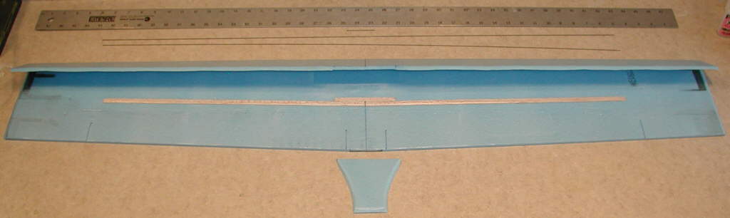
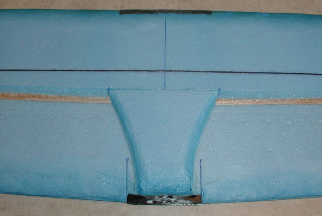
[Above]: After cutting out the wing blank, the center balsa spacer strips are cut and glued in place; I used foam safe CyA for this step.

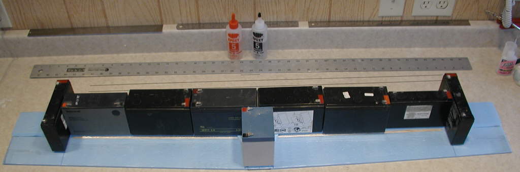
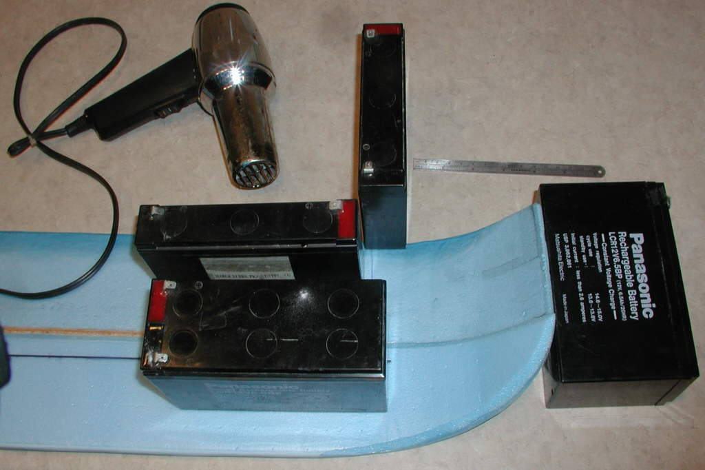
[Above]: Next, the upper layer is glued to the balsa spacer ONLY; I used 5 minute epoxy for this step. The collection of old Gel Cell batteries are being used to weight everything down flat while the epoxy sets.

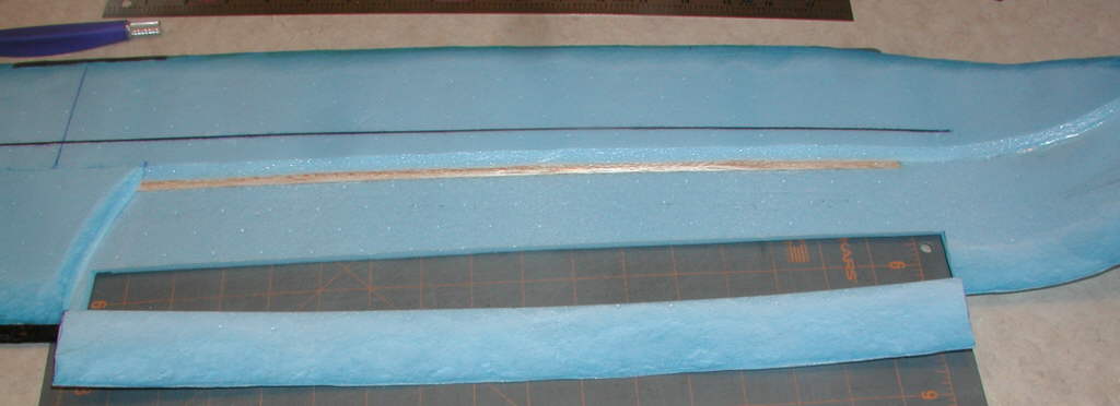
[Above]: Thinning of the Bluecor trailing edge is begun; (I later decided to use light balsa aileron stock rather than the Bluecor Ailerons, so I could have skipped this half-hour long process.)

[Above]: A french Curve was used to trim back the wingtip leading edge.
Install the cap spar rods next, one at a time. (I lacated the spar cap rods at 38% of chord on this wing, since I expect this wing to fly well when balanced about there.) Draw a shallow groove with a ballpoint pen where the rod will be glued, being careful to not cut the Bluecor's surface film. Then 'woodpecker' a line of holes along the bottom of that groove. Next, apply a line of thin foam-safe CyA glue in the groove, and set the spar cap rod in it. Weight it down flat while the glue sets.

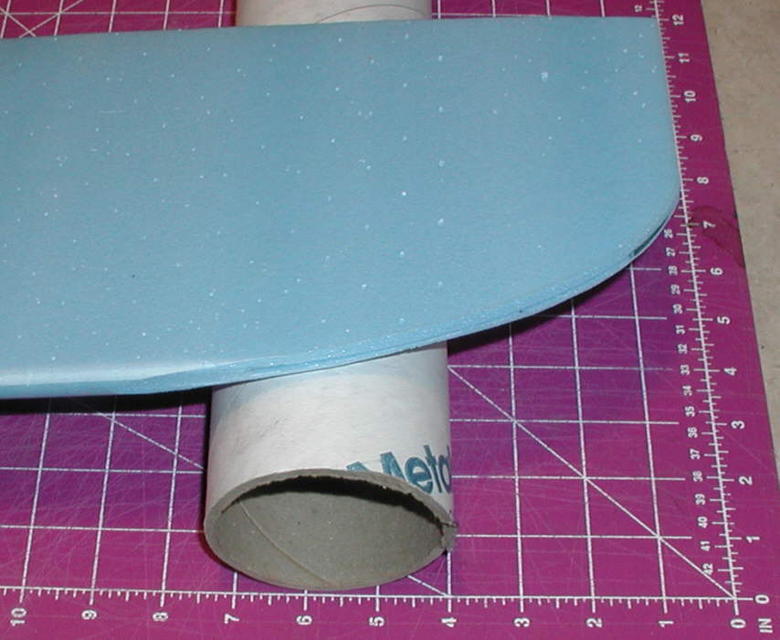
[Above]: Once your spar cap rods are glued in place (not shown in this photo) roll in the upsweep at each wing tip. I roll the bluecor over a 3" diameter tube for a smooth upsweep.

[Above]: Use a heat gun to 'temper' and firm the bluecor upswept tip areas while keeping it supported at the desired amount of total upsweep at the end; I'm using 2-5/8" of upsweep off the work surface on this wing build.

[Above]: Once the layers of Bluecor are shaped and heat-tempered in thwe wingtip areas, trim away the excess upper layer foam as appropriate. Then use hot melt glue or epoxy to glue the upper layer to the lower layer. Once glued, use the heat iron to heat-form the wing tip edges.
Use the heat iron to also round down the upper surface of the wing's leading edge to form more of an airfoil shape. The underside edge is also slightly shaped upward; the idea is to have the new leading edge at about 25% to 30% of the wing's thickness, so it will generate more lift and penetrate winds mre cleanly. Avoid forming too sharp a leading edge, as it will result in greater pitch sensitivity.

[Above]: A rear center section doubler has been glued in place and then heat-formed / contoured. One section of 1mm CF ros 2" long, which had been cut off of one of the cap spar rods, was glued along the bottom trailing edge of the center section of the wing before the heat forming was done von this section. Then some Carbon Fiber 'tow' was wrapped around the trailing edge, ironed on, and glued in place with foam-safe CyA glue.

[Above]: Cut away the Bluecor ailerons - or the openings for the Balsa ailerons if you are going that route. Note that when I cut away this aileron, there is some up-curving, due to the heat affects on the upper surface of the Bluecor. While you can remove this curvature by working carefully with the heat iron, it's a touchy job; I decided to use light balsa ailerins, 1/4" thick x 1-1/2" wide, on this wing instead.
After beveling the leading edge of the balsa ailerons and sanding the aileron hinge line on the Bluecor wing to match, I made a pair of 1/32" birch plywood control horns which are than glued to the entire inboard end of each aileron. (See photo below.)

[Above]: Here is the new wing, mounted temporarily on a HLG Pod and Boom fuselage. The ailerons are hinged with Scotch "Extreme" cross-filament tape in threee places on each aileron's top surface. A 1/2" wide section of the same tape is used on the underside of each of those tape hinges, too.
This HLG fuselage's EPP nose section will be further shortened and shaped to a slim streamline profile once all servos are set, and the balance / placement of the receiver battery is determined.

[Above]: This is another view of the upper surface of the wing, showing the aileron control horns and hinging tape placement.

[Above]: A view of the underside of the wing, and the temporary EPP foam fuselage's shape. A .157" diameter AVIA pulltruded CF tube is used for the tail boom; the bluecor tail members have their edges thinned and firmed by the heat-forming technique.

[Above:] The new "DANCER", which is now the name for the resulting complete aircraft design. The new design fuselage, designed to fly the 2nd wind prototype, uses Yellow 'AquaRider' foam for the forward body, a 28" long AVIA .157" diameter tubular C.F. tail boom, 6mm thick charcoal grey Depron for the horizontal stabilizer and elevator, and 3mm thick Depron for the vertical stabilizer and rudder.

[Above:] The heat forming techniques work very well on the Depron tailgroup members to round and firm and streamline the leading edges, while the trailing edges of the elevator and rudder were substantially thinned to about 1/16" or less. (Depron and Bluecor are heat-shaped at about the same temperature - somewhere around 340 to 350 degrees F.)

[Above:] The AquaRider foam material used for this fuselage also heat forms very well (although at a much lower temperature that when heat-forming either Depron or Bluecor.) Both the nose area and the trailing edge of the fuselage body are heat formed and streamlined.

[Above:] The step on this wing's upper layer is now also at 50% of chord, and has been built out to a 90 degree square rear edge. The Yeellow and black paint I used is KRYLON H2O; the Fluorescent orange paint used on the wing tip areas for enhanced visibility is "Odds N Ends" spray enamel; it works fine on Bluecor.

[Above:]The photo avove shows how the vertical and horizontal stabilizers are mounted; the V. Stab. is shorter and elongated in comparison to the "Slim Beagle" fuselage design. The Horizontal stabilizer is also 1" narrower, and elongated, for improved aerodynamics. Rudder and elevator widths are reduced to 2" on the "DANCER". The motor is another 10 wind Y GBv CDROM motor; this wind flys these aircraft well using a GWS 6x3 DD propeller. The fuselage height is just high enough to have an extra 1/8" clearance between the tailboom and the propeller tips. The overall length of the aquarider foam is just under 6", to allow balancing with a 2S 800mAH battery pack well forward in the nose

[Above:] The underside is colored for good visability against either blue sky or clouds.

[Above:]Wing mounting is done with rubber bands. The wing mounting bamboo pegs are inserted through 1/32" birch ply side plates; (the 3/32" holes are not drilled yet in this photo). There are also top 'spreader' plates between the side plates, to keep the foam from deforming or compressing in these areas. Two 1mm diameter CF rods were also epoxied in place ater being sharpened and then inserted through the foam, running up from the tailboom to the outrer edges of the rear wing mount plates. This pair of lightweight rods 'triangulates' the wing mount attachment to the tail boom for a more rigid wing positioning in relation to the tailgroup.

[Above:]You can see in this photo that the tailboom extends all the way forwward into the battery bay area, to minimize unwanted flex in the foam fuselage.

[Above:] These are the Depron Tailgroup menbers, hinged and heat-shaped, ready to be epoxied to the tailboom.

[Above:] DANCER ready to fly! View to the west from the KING slope flying site in South Park, Mosquito Range, Central Colorado Rockies
The Krylon H2O paint does add weight, but it bonds well to the BlueCor without attacking the core foam, so I have been using it. I've never come across the 'floral spray'... where do you buy it? It sounds very interesting, so I'd like to try it.
Another note of interest: the 3mm and 6mm grey Depron which I used for the tailgroup on the DANCER responds **very nicely** to the heat forming techniques, using the covering iron! Temperature setting is very clse to that used for the Bluecor- about 340 to 350 degrees F. It's possible to have nicely rounded leading edges and well-thinned trailing edges in a modest amount of time.
The Aquarider foam melts at well below this temperature, so a setting of ~280 F might be closer to what's appropriate when heat-shaping that material. (EPP does not work with the heat-forming / compressing / tempering techniques; it just melts and likes to stick to the teflon surface of the iron.... so it's a process of carving and sanding to streamline the EPP. It does have other structural qualities that I like better than the AquaRider foam, however, so each has it's place.

[Above:] Another view of DANCER at the King slope flying site, looking to the Northwest at another section of the Mosquito Range, with Boreas Pass in the center of the skyline in the distance.

[Above:] Ready to fly weight is about 9-7/8 ounces after taping & trim, balancing at ~38% of chord; flying very smoothly! Wing loading is just under 4.5 ounces per square feet.

I drove up to the top of the KING slope flying site with DANCER to do some test flying in the slope winds. The winds were fairly strong, running from ~15 MPH to over 20 MPH on the wind meter... but from a poor direction.... King faces almost due west, but this day's winds were out of the NNW, towards the rather narrow end of the ridge, which also has a much lower slope angle, and resulting weaker lift.
So after shooting some photos, I launched DANCER for it's maiden flight anyway!
It handled the marginal conditions very smoothly and predictably! Climb is smooth and strong, inverted flight is good, and roll performance is what you'd likely look for in a lightweight hotliner. Response to rudder & elevator are positive and smooth.
The balance is presently at 38% of chord; I'll play with shifting it back toweards 40% when I get a chance to fly thermals in lighter air, and try to define the exact 'sweet spot' for the balance on this wing. Right now, it's very smooth with no hints of pitch sensitivity, even though the wing's leading edge now has a slightly tighter radius than the SLIM BEAGLE's wing.
For having only a 4-1/2 ounce wing loading, this light DANCER is performing very nicely on the slope in far less than 'ideal' slope wind conditions.
So the new DANCER fuselage / tailgroup design is handling very nicely!! A battery compartment and hatch cover were built on the left side of the nose. The nose area around the battery bay is reinforced with 3M Extreme cross-filament tape before the clear plastic hatch cover plate was taped in place. The black 'windows' and logos on the vertical stabilizer were added to dress it up a bit... (then it was time to fly!)
Notes of interest: I'm presently using from 1/16" to 3/32" of 'droop' at the trailing edge on the 7" chord wing. (I've installed Dubro mini EZ connectors on the aileron horns so I can play with and easily adjust this setting.)
~~~~~~~~~~~~~~~~~~~~~~~~~~~~~~~~~~~~~~~~~ Here's an excellent article on: A Physical Description of Flight © by David Anderson, Fermi National Accelerator Laboratory, Ret. & Scott Eberhardt, Dept. of Aeronautics and Astronautics University of Washington, Seattle WA : http://home.comcast.net/%7Eclipper-108/lift.htm
~~~~~~~~~~~~~~~~~~~~~~~~~~~~~~~~~~~~~~~~~
From Jeff Reid's writing in the following linked article titled "How Wings Generate Lift", we see a very important point brought to our attention: that 50% of the lift of a wing is generated in the first 25% of the wing chord. This emphasizes that to achieve greater glide efficiency, it's very necessary to pay closer attention to shaping the airfoil in that front 25% of the wing.
If you look at the RG14 airfoil, you may have an idea of some of the wing shape aspects that I'm trying to employ to reduce drag while ending up with good performance and efficiency across a wide speed range. The KF step on top of the wing reduces drag if effectively implemented, and at the same time reduces air separation. The eliptical upswept wing tips move the wingtip vortexes up and away from the wing's upper surface, so that more of the wing surface is actually generating lift.
That's why shaping the leading edge area of the wing is important; but it's also why I wanted to nail down the aspect of the 90 degree top step first, before completing the L.E. shaping on this #2 wing. http://www.physicsforums.com/archiv...hp/t-107565.htm
~~~~~~~~~~~~~~~~~~~~~~~~~~
written 5-01-2007] Originally Posted by Tony65x55
Question by Tony: "Viking, nice bird. Looks like you have a fine flyer. With the wing mods you completed, does it fly as good as the last one? Did the LE mods have the desired effect (if you posted this, sorry, I missed it) Thanks, Tony
[BKS Reasponse]:)I had thinned the leading edge substantially (heat - forming / compressing using the covering iron) before I painted the wing. To be more specific: I shaped & compressed the upper surface foam, contouring it back for ~1-3/4", shaped the leading edge radius at roughly 25% to 30% of the wing's total thickness, and also shaped / rounded up the first 1" of the chord on the underside of the entire leading edge, giving the airfoil more of a 'Phillips Entry' for smoother handling and penetration at high speeds, as well as clean efficient gliding at low speeds. Some of the photos are sharp enough to show the leading edge's contouring, as well as the extensive thinning of the upswept wing tips and the trailing edges.
Competition Glider guys know 'it's all about the airfoil', and the RG14 is a superb thin high speed glider airfoil. (It's also excellent for lightly loaded foamies which you want to have the ability to both penetrate wind, and to glide efficiently in light thermal lift. At a heavier wing loading, the RG15 would be more appropriate; in a more flat bottom airfoil, the E205 has served me well, but it was thicker than I wanted for the DANCER wing's build.)
Print out a copy of the RG14 at 7" chord in the Profili software (free evaluation copy does this OK), then look at it- make templares from it to use if you want- and figure how to sand and carve away and heat compress the excess foam that doesn't fit within the airfoil shape template, and you will have a good start at forming a cleaner, more efficient glider wing from Bluecor, Depron, etc.
I wanted cleaner penetration and more lift while staying with a thin wing. The beauty of DANCER's wing is that it starts with two 6mm layers of FFF / Depron, and a 1/16" thick spacer to get to ~7.5% thickness - basic and fairly easy for the novice builder to put together without warps or twists!
Jeff Reid, in the writings on the PhysicsForum discussion I linked for everyone, pointed out something that should be carefully contemplated:
"50% of the lift of a wing is produced by the front 25% of the chord of a wing."
That emphasizes how significant the shaping of this section of a wing can be when we're looking for efficient glide, as well as wind penetration. If you don't shape it, then that front 25% of the wing chord is probably not doing as much as it could, and the glide on a glider wing will not be as efficient as it could be.
For 3D aerobatic powered park flyers and planes that are intended for hovering and high-alpha maneuvers, symmetrical and flat plate wings perform fine... but for really EFFICIENT gliding as well as smooth wind penetration at higher speeds, the shaping of the front 30% of the wing can contribute dramaticly.
The 90 degree K-F step, when built at 40% to 50% of chord, helps keep air from seperating from the surface of the aft 50% of the wing's chord in the areas where a step is implemented. This is why it helps KEEP the rear part of the wing from loosing it's ability to generate lift at slower speeds and at somewhat higher angles of attack. But it doesn't affect the air flows / pressure differentials forward of the step very far, in the front 30% to 40% of the wing's chord....
That's what the front 30% section of a wing's airfoil shape, and the resulting 'camber line' of the airfoil, can do when shaped. Figuring out how to accomplish it in a fairly simple build using FFF / Depron material is what the DANCER's design evolution is all about.
~~~~~~~~~~~~~~~~~~~~~~~~~~~~~~~~
You asked about comparing the first constant chord wing, and the DANCER's tapered chord wing; I need another couple thermal flying sessions before I'll offer that evaluation.
First I need to fine-tune the balance on Dancer; it's a bit forward of ideal for most efficient thermal gliding capability. I'm looking for neutral elevator trim, and both blalnce and declage are involved in achieving that. I'm looking to get towards a bit LESS pitch stability than I have now for more efficient glide... it's a trade-off that is exactly a 'balancing act'!
I built in slightly more positive wing incidence on the DANCER's fuselage than on the "Slim Beagle" fuselage, so I want to compare those, and test by shimming the T.E. of the DANCER's wing to remove a bit at a time; a minimal wing incidence angle of +1-1/4 to +1-1/2 degrees relative to the horizontal stabilizer should be ideal for DANCER's RG14KFv airfoil, and it's intended wide flight performance envelope: light hotliner to thermal floater.
I may try to get in some thermal flying today... it's a brilliant Colorado Blue Sky morning, & good thermals should be forming by 10 AM... have to take some time away from work to take advantage these ideal flying conditions!!
More soon! Whatever you do, howerer you do it, HAVE FUN doing it!!
[Question]: "Viking, are you skinning your FFF before the heat shaping?"
[BKS Response]: For the extensive shaping I'm doing on the wing leading edges, peeling the Bluecor might help; the surface film can be also heat formed without removing the film, but if you are melting a lot of it, it does build up a higher density. It can be compresed & smoothed, but removing it selectively would be worth doing in certain applications..
For rudder & elevator trailing edges, I would not remove the film; I'm loking for firmer high-density edges there.
DEPRON is forming very nicely; carving / sanding to a rough oversize form, them finishing with the covering iron to a smooth finish shape might be the ultimate approach, rather than heat-compressing a lot of volume of foam.
[5-01-2007]: Friends,
Dick Kline asked me yesterday if I had any video of DANCER flying. I regretfully told him that I mostly fly alone, so getting video was a challenge.
But then, later this morning, I got to thinking of the tripod I had sitting in the corner, and so I decided I'd set up my digital camera and give it a try. I had never tried this before, and if you have shot video with a digital camera, you already know that the frame rate is slow when shooting video at 640 pixels wide...
The other issue was trying to have an idea of the modest sized 'window' of sky that the camera captures, and to try to fly most of the time within that window... another first for me!
Wind noise is excessive on the video, as another storm front was rapidly moving in- not thermaling conditions. Most of the flying is more 'hotliner' flying rather than gliding, but you'll get an idea of the performance capabilities, from the hand launch to the hand catch.
This is only the second day that DANCER has been out & flying; final balance tweaking remains to be done on another quieter day. (I didn't complete the work I planned to do this morning until the storm clouds were on the horizon and beginning to march across the Park at an impressive rate!)
So if you have high speed internet access, and you don't have a problem waiting for this 56MB file to download off my server, here's the link- let me know what you think!
NOTE: This may take a while to download from this server!
~~~~~~~~~~~~~~~~~~~
FEEDBACK Comments:
"AWESOME!!! INCREDIBILE!!! MAGNIFICENT!!!"
"Talk about Big Sky... the setting was great. And the DANCER looked very graceful. It's seems to move through the air effortlessly. I am just so impressed with everything.
How does its penetration through the air compare with other airfoils?
Thank you so much for this great big pleasure.
If I can help you in any way, please let me know. You are amazing!!!! "
Dick Kline
[BKS Reply]: Comparison? I'll just say this: in it's size and weight class, it stands alone! Penetration is exceptional for a wing that is so lightly loaded; 4.5 ounces per square foot is VERY light, yet it's handling the slope winds very nicely. The power system is well matched to this wing's capabilities- another piece of the overall performance picture.
I just posted the link to the video on RCGroups, so others can also view it.
Thanks for all of the kind words & ongoing support and encouragment!!
~~~~~~~~~~~~~~~~~~~~~~~~~
[RCGroups member comment]: "Looks very nice Viking!!! The speed looks great; it looked like the Dancer had no trouble at all penetrating the wind. How windy was it?
Great job!!"
[BKS Response]: Thanks!
The winds weren't all that bad - maybe peaking at 15 MPH; on the video you can see how the DANCER was being rocked in my hand before I launched; but it was easy for the DANCER to fly through, a bit turbulent during slow low landing approaches, but not conducive to allowing lower level thermals to shape up decently. The wind noise in the camera's microphone is quite noticable... (this is the first flying video I've set up to shoot.)
[Added 5-5-2007]
Friends,
The 7.5% thick wing with the KF step treatment on top at 50% of chord is flight proven; it flies very well.... but it's sleeker and faster than what many aircraft designs may want- especially for park flyers designed to fly in smaller areas.
The question of how to build a thicker wing, using sheet foam - Bluecor and / or Depron, and fairly simple assembly techniques, has been on many people's minds. The potential problem with thicker wings is that they may have a greater drag penalty when the step depth exceeds ~60% of total airfoil thickness at the step. This in turn could result in reduced flight / glide efficiency.
But the concept of using a second step between the 50% of chord point, and the trailing edge, merits investigating... (and it lends itself well to working with layered sheet foam materials, too!)
Below is a diagram of the new prototype that's on the building table now. It has a total thickness of 9% of chord. The wing's overall dimensions are 48" span x 7" chord [before the wing end areas are upswept], so that direct comparison test flying can be done, comparing against the other two wings built at 7.5% thickness for the DANCER.

1>The bottom layer is Bluecor (or 6mm Depron).
2> A 1/16" thick x 5/16" wide balsa strip, 39" long, is added with it's rear edge at the 50% of chord line.
3> a 3mm thick sheet of Depron, 1-9/16" wide by 39" long is then overlaid as shown in the drawing, extending over the balsa strip in front, and 1-1/4" behind the 50% of chord line. It also has a 90 degree trailing edge step. This places the secondary step at 68% of chord.
4> Another strip of depron, 5/8" wide x 39" long, is laid in with it's front edge back 7/8" from the lower main sheet's leading edge. This is included to help form the forward curved shape of the airfoil, and the resulting "Camber Line", drawn in red on this diagram.
5> The upper layer is another sheet of 6mm thick Bluecor (or Depron) that is slightly rolled to form the curvature of it's upper surface before being glued to the three contact lines. It has a 90 degree step angle, with it's rear edge at the 50% of chord mark. It is then glued in place along the three contact lines: leading edge, front depron spacer strip, and at the step.
6> The wing tip areas have been rounded back to match the profile on the previous DANCER wings, and will be upswept an equal amount. 1mm CF rod cap spars will also be added on top & bottom; since they also act as "turbulator spars", starting the surface boundry layer air turbulation process, I plan to locate these at 33% of chord, as I did on the first DANCER wing.
7> I'll again use light weight balsa aileron stock, with each aileron being close to 18" long.
I may be able to complete this new prototype wing and have it ready to fly later tomorrow if weather conditions permit.
(It's still snowing lightly as I write this, so I'll have to see how the weather shapes up for a test flight tomorrow afternoon. I'll report the observations when test flying is completed.)
The fun continues!!
[*** OH... the dashed gleen line in the upper rear section of the airfoil? That's my conception of the 'virtual airfoil' boundary between the lower turbulent air that remains turbulated and attached to the wing's rear surface, and the higher speed / 'lifting' airflow above that boundry.... At this point, it's simply how I conceptualize it for now!] ~~~~~~~~~~~~~~~~~~~~~~~~~~~~~~~~
[Originally Posted by tolladay]:
"Beautiful work Viking. The drawing really really helps to visualize, especially for us poor artists types who see better than they read.
I'll note that you did not include the negative reflex of the ailerons in their final position, or will you be testing this as well? (knowing you, you'll be testing 3 other things to boot )
Looking forward to hear about your progress.
re: thinner wing. For a while I've been wanting to design a fairly slick (as in not draggy) glider out of FFF. This was the initial reason why I started asking about your wing as it looks perfect for this application. Maybe even an 8' span wing (two 4' sections joined at the middle) with ailerons on the outboard, and flaps in the middle for full camber manipulation.
Who knows? Maybe the double step wing will perform even better."
~~~~~~~~~~~~~~~~~~~~~
[BKS Response:] Tolladay,
I'm expecting this airfoil / wing to also fly better at higher speeds & in slope winds, and also ride thermals better, with a bit of trailing edge droop set in the elevons- maybe only 1/16" to 3/32" max. at the elevon T.E.; It builds out flat fairly easily. Yes, everything will get tested!
On an 8' span wing, spar structure design would be more of an issue. There's excellent structural strength / rigidity at the 48" span size using just the two 1mm CF rod 'cap spars' bonded to the top & bottom surfaces of the Bluecor , as they can neither stretch nor compress... the result is a structure similar to an I-beam, accomplished with only .08 ounce of material.
The thinner 7.5% thick wing will very likely test out as better for handling higher speeds, and will have better wind penetration capabilities at light wing loadings. This 9% thick wing is being tested for slower flying designs.
The simplicity of build is also being pursued; stacking pieces of sheet foam to end up with a higher performance wing / aircraft is something that any foamie builder can do. (It's a nice alternative to hot wire cutting of foam cores!)

Above: This photo shows the internal strip spacers; the 1/16" thick balsa strip is under the front edge of the rearward wider 3mm thick piece of grey Depron.

Above: Top layer of Bluecor is shaped, has the curvature rolled in, and is ready to be glued in place; I used 12 minute epoxy for this job so I'd have enough time to apply the glue to the three contact areas. The front narrow 3mm Depron strip has also been heat-compressed along the front edge, for better contact & final airfoil shape.

Above: Epoxy has been applied, and the top layer is in place, throughly and evenly weighted down with old Gel Cell batteries while the epoxy sets up.

Above: Next, the wing tips were shaped into the upsweep, with the outer edge ending up at 2.5" off the building surface. Hot melt glue was applied between the two Bluecor layers, then a heat gun was quickly used to heat-temper the upswept curvature into place. The excess Bluecor was then carved away close to the final form for the Covering Iron's application to achieve the final heat-formed contours.

Above: This photo shows the final smoother heat-compressed and tempered leading edge.

Above: Heat-formed Bluecor ailerons are hinged in place. The top rear center doubler is in placed and shaped, and the 1mm CF rod spar caps have been glued in place at 33% of chord. Balance should be close to 40% of chord for most efficient glide.

Above: CF rods have been hot-melt-glued to the center leading and trailing edges and overlaid with Scotch Extreme tape. Aileron servo and linkages are in place and set, ready to fly!
Weather has been quite snowy late today, so the flight test report will have to wait for a better day!
[Added Monday afternoon, 05-07-2007:]
Friends,
Despite snow fluries still drifting down, after running to town in early afternoon to ship a package, I decided to get in a short initial test flight on the new 9% thick wing. Light was somewhat flat but bright, & the flurries weren't too thick; best of all, the air was close to calm and smooth.
Initial evaluation? This wing is really SMOOTH! I'm going to say at this point that the glide is flatter, and it's able to glide more slowly than the 7.5% thick DANCER wings (with their much thinner leading edges and lower airfoil camber lines) without beginning to 'mush'.
Since the world is covered either in slushy snow or the mud on the dirt road I'd launched from, I was gonig for a hand catch... but on the first five setups, this bird just wasn't coming down... so I'd power up and go around again! I got a perfect grab on the fuselage nose as the next snow squall was moving in thicker, and called it enough for right then.
So even though this aircraft (9% DANCER DS wing on the "Slim Beagle" fuselage) is 1/4 ounce heavier than the 7.5% thick winged DANCER, it appears to be gliding flatter / even more efficiently, glides cleanly at slower speeds, and has less pitch sensitivity than the thinner wings with their sharper leading edges. It seems to fly a bit slower under power, but is smoothly responsive.
Balance is at 41% of chord; flying weight of 10-1/8 ounces on a 2.22 Sq. Ft. wing = a wing loading of 4.56 ounces per square foot.
Is the secondary step further reducing drag to improve the glide? Quite possibly; that was the intention.
How much of the improved slow speed glide performance is due to the thicker wing with it's well shaped forward section and the higher camber line? A significant portion, undoubtedly.
The overall result is a sweet flying wing that handles like it's 'on rails'..... smooth!
More soon!!
Quote: [Originally Posted by Tony65x55 on 07-16-2007] "I'd start at 20% Based on a 16" wing root that would put the CG at 7" from the LE, measured at the root. The KFm usually likes a CG more aft than most. " Tony
[BKS Response:] I'll offer a bit of further insight if I may:
On the DANCER, with the top KFm step at 50% of total chord, the ideal/ most efficient thermal gliding balance is at about 40% of chord. I'd expect a conventional RG14 Airfoil, of similar leading edge shape and layout & at a thickness of 7.5%, to glide well with the balance set at 30% of chord, so the KFm step addition back at 50% of chord seems to effectively move the center of lift back about half of that difference- to 40%.
My SPINNER is an aerobatic 3D type design, and the first two were built with flat plate Bluecor wings. Balance is ideal at 30% of chord. When I built the third SPINNER, I tripled out the leading edge back to the 30% of chord mark, with a well rounded leading edge and a 90 degree step at the back edge of the added layers at 30% of chord (on both top & bottom.) This aircraft still balances & flies very well with the CG at 30% of chord (because the KFm steps were not located farther back on this wing.)
It flies more like a thin symmetrical wing, rather than the previous flat plate wings, largely due to two aspects: first, the well rounded 3/4" thick leading edge on the wing is less pitch-sensitive. Second, with the very rigid wing structure resulting from the triple layer build, there's no 'camming' of the wing compared to what is seen on thin flexible flat plate wings when transitioning from up-loading on the wing to down-loading.
In working with FFF materials, it's really nice to know that there is no drag penalty when building in the 'discontinuity' which we've come to refer to as the KFm step (- at least, no drag penalty if the step is not too deep?)
And in fact, there are indications that the wing can possibly fly a bit faster / more cleanly than a 'fully shaped conventional airfoil' *IF* the KFm steps are implemented properly..... an observation which still confounds the classic old-school aerodynamicists... (which relates to why golf balls fly farther with their many little dimples than they can be driven without those little dimples / 'discontinuities' on their surface!
This Wednesday the writer from Popular Science is coming up to interview me about the KFm revolution in Foamy RC design, and to see the DANCER do it's thing... it should be an interesting day!
The Fun Continues!!
VIKING
[Discussion posted on 07-18-2007: ] Quote: Originally Posted by davereap
..." It does make me wonder how critical it all is, is there a minimum usefull step depth, or a maximum.
From trials the chord %ages that improve the glide have been found, but with some planes they are including the ailerons and on some they dont. Some use top steps some use bottom steps. Some planes are fast some slow. There are so many variables that it is difficult to specify what will work best for a particular plane.
What is not in dispute is the improvement you can get with the step.
It is good for us all that lots of variations are being tried, the more results we get, and even poor results count, the better our understanding will be of the whole thing."
[BKS Response:] Dave & friends,
Sailplanes sometimes use either "turbulator spars" or the addition of "trip strips" on the forward section of the airfoil's upper surface to effectively turbulate the boundry layer air, thereby reducing air separation... so the minimum height / thickness of a 'discontinuity' / step to achieve this effect can be quite minimal. The nice thing we now know that's relavent to building Foamies from layered sheet FFF / Depron, etc., is that there is not an observable 'drag penalty' from building the step in most cases, at the speeds at which these foamies fly.
I believe we can experimentally demonstrate that when a optimally located step (-let's say, top step at 50% of chord) exceeds a certain height / thickness, that it may generate more drag than a lower step height would generate on the same wing. This is perhaps why such wings at 7.5% to 8% thickness are understood to generate lift and still glide fairly efficiently, but thicker wings with deeper top steps do not perform as well / glide as efficiently.
My third DANCER wing was built at 9% thickness as a test, but was built with a staged double step, to keep the depth of the steps shallower. (I wanted an airfoil with a higher camber line for slower flight tasks, which would still fly & glide with minimum drag and therefore glide very efficiently.)
Flight tests are still ongoing. In the early half of May, I flew on days where this thicker wing seemed to be able to glide in soft lift & dead air at lower speeds & with less sink than the 7.5% thick, single step wing could in the same air. (This was in the 16% lower air density of my 'home' flying area here in the central Colorado Rockies at about 10,000 feet elevation.)
In comparison, I flew both of these wings in Wisconsin during the latter half of May. Skies were hazy / lightly overcast & I was not flying in a area that was generating thermals, so I was flying in thicker 'dead' air. In those conditions, the 7.5% thick DANCER wing outperformed the 9% thick wing. It simply felt more 'lively' and responsive. (Elevation there is roughly 600 feet ASL )
TOLLADAY's experiment of adding the step to the underside of his undercambered wing on his Cub was very revealing; he found that it produced a heavy drag penalty, besides increasing flying weight / wing loading, without any perceived desirable affects.... (- hopefully I've summarized his brief report adequately!) So from this we see a dramatic demonstration of how adding a step can possibly degrade the performance of certain designs.
When in doubt, build it several ways & test fly it... that's the only way to really prove what offers the optimum performance.
The glide efficiency performance testing is where I've focused some of my design & prototyping work, since the results are most obvious in the degree of power-off glide efficiency achieved by variations.
For other designs / performance tasks, increased drag may not be an issue of concern. Whatever anyone chooses to build & fly, have FUN doing it!!
VIKING [Bruce Stenulson posting as VIKING60 on RCGroups]
I had a bit of time yesterday afternoon, so I threw together this wing; it's 33" span x 7" chord- identical to the wing size on all 30+ of the 'EPP Beagles' that have been built in this region over the last 20 months; I chose this size for performance comparison purposes. However, due to the extra material and aileron servo & linkage, there's a weight increase of about 2 ounces on the new KF Variant wing... (the origional undercambered wing was only 1-3/4 ounces.)
I wanted to try another thicker KF variant wing, using the double staged step technique. This approach actually results in a 10.6% thick wing at the maximum thickness point at 35% of chord. (The DANCER wing, in comparison, is only 7.5% thick.)
Photo # 3 below shows the placement of a 3-1/4" wide 'spacer' layer of bluecor already mounted in place. This effectively produces a secondary staged step at about 70% of chord- the rear edge of the center Bluecor spacer layer.
Since I actually wanted to test-fly a wing with the primary step at 50% of chord, but with the maximum airfoil thickness at 35% of chord, I added in a 1/16" thick strip at the 35% location on top of the center spacer layer. (The photos should clarify both the simple layup process, as well as the resulting airfoil shape.)
Prior to closing up this folded wing, I rolled a bit of under-camber / curvature into the underside of the upper forward layer, to achieve a nicely curved upper forward surface to the airfoil.
ALL assembly was done with low temp hot melt glue; this made for a very fast build! There's about one full stick of glue in this wing- a fair trade for the speed and ease of construction. (The aileron horns were the only thing glued in place with foam-safe CyA glue.)
I first flew this wing last evening on one of the classic "EPP Beagle" fuselages, as shown in photo # 2 below... but the balance wasn't right when first mounted on that fuselage's wing mounting platform, so flying this new wing was a bit of a handful... fun, but not 'dialed in' - not at all suitable for a pilot with novice level skills. (The DANCER wing also was less than great when flown on that fuselage for similar reasons, so moving the battery to shift the balance substantially would have been necessary for both of these KFm wing upgrades.)
After 'sleeping on it', I woke up with two changes to make quickly: adding the wing tip plates on the wing, and installing this new wing on the second generation "Slim Beagle" fuselage.
Oh, MY, what a fine and pleasing difference!! The Slim Beagle has a bit hotter wind motor, turning a 6.3x3.5 prop, for a much more suitable airspeed for this wing. Add in the wing tip plates, fine-tune the balance, and suddenly, this "HOTDOG" wing comes alive!!
It climbs smoothly & predictably, rolls cleanly, loops nicely- both inside & out, of course- and flies inverted with only modest forward pressure on the stick.... not too shabby for a ~ flat bottomed wing! The power-off glide is fairly respectable, while the slow speed landing handling is docile and very managable- just what a novice pilot would love!
I had purposely left the folded leading edge alone, so for a little while longer it's still shaped like the standard fat round profile of the FFF's fold. I'm certain that shaping the leading edge would further improve the handling. The trailing edges are also full thickness- no thinning or shaping done to them at all yet; doing so should further improve the handling and glide efficiency of this quick-build "Hotdog" wing, but I wanted to do the changes in simple steps, test flying after each change, to evaluate the progressive contributions to the handling performance.
Other than the final wing shaping / streamlining, I can easily see myself increasing the motor power output- this wing can easily use a lot more! I may start by simply going to flying a 3S LiPo in place of the 2S, re-adjusting the prop size & pitch to get the performance this wing can deliver.
(No, it's definitely not your Grandmother's Beagle anymore!)
The Fun Continues!!!


[QUOTE=B] ...." The glide wasn't as good as I expected, but I can't contribute that to anything in particular. Nice, slow parkflyer![/QUOTE]
B,
Designing & flying with the light IPS or LPS power systems is fun- the aircraft definitely fly 'on the wing', not 'on the prop'. But with a modest amount of power, the setup for better performance benefits from some fine-tuning.
Four things can be looked at for glide efficiency / drag reduction:
A> Fixed blade props which windmill on the glide cause more drag than a stationary prop; it's hard to do anything other than using an ESC with a prop brake which can stop the windmilling (or a folding prop, which may not be suitable for many designs like yours).
B> The nose profile may be blunt enough to be causing added drag, but may not be as significant as other setup factors. That's something you can consider playing with in future designs if reduced drag is a priority.
The next two may be of more importance:
C> Variations in the declage (horizontal stabilizer to wing incidence) and balance point will have a profound affect on glide efficiency.
D> The wing's cross-sectional profile will tell us a lot about whether the resulting airfoil will glide cleanly, or just so-so. (A photo of the end of the wing will tell a lot.)
[I've built some KF variant top step wings that certainly do NOT glide as well as a single layer undercambered wing, and were substantially heavier from the double layer construction, increasing wing loading with the resulting performance decrease. ]
For examples on wing profile aspects:
1> A blunt leading edge will have more drag and less lift on glide; on the opposite end of the spectrum, a thin sharp leading edge can be far more pitch- sensitive. 50% of a wing's lift is generated by the optimized shaping of the front 25% of the airfoil, and adding a KF step will not really help a wing generate more lift...
[NOTE: The KF step can only help turbulate the boundary air layer aft of the step location, to possibly help keep the lifting air from seperating from the wing within a slightly extended range of angles of attack. IF properly implemented in a well designed airfoil, it may result in reduced drag... but if not optimally implemented, it may in fact increase drag.
TECH NOTE: Turbulating the air farther forward on the airfoil to minimize leading edge separations has additional benefits; that's why turbulating spars have been in use in building sailplanes and free-flight aircraft, and why using 'trip strips' at ~15% of chord has been known to work so well on sailplanes... This is a technique that's been in use on competition sailplanes since the 1960s (or before) for turbulating the boundary air layer to keep the boundary layer air / lift attached. These are thinner structures than the classic KF step, implemented in more ideal locations, but have been implemented effectively for the same purposes.
[Side note: The writer for the upcoming Popular Science article had never heard of 'trip strips' and 'turbulating spars' prior to coming to do my interview & see the flight demonstrations; she admitted to having no background in aerodynamics, so she was writing the article based on the interviews she was doing. ]
On the 7.5% thick DANCER wing, the 1mm CF rod spars are exposed about 60%, placed at 33% of chord on both the top & bottom surfaces; these then act as 'turbulator' structures 13% ahead of the step at 50% of chord, thereby beginning the boundary layer turbulation process farther forward on the airfoil. The further addition of a thin 'trip strip' or another turbulator spar at 15% of chord might further enhance the performance of the DANCER wings; they already have superb glide efficiency. (Other further performance enhancing aspects will be published after further prototyping and test flying.)
2> Step height greater than a certain amount may begin to have more of a 'drag pocket' effect in some flight modes; After playing with declage & balance, you might consider testing the effect of adding a secondary step behind the primary step to see if it reduces drag and thereby increases glide efficiency. (See the DANCER 9% thick wing and the HOTDOG 10.5% thick wings for examples that are working, using dual staged steps.)
Again, shifting balance to find the 'sweet spot' - [somewhere around 38% to 40% of chord on a wing with a top KF step at 50% of chord]- will have a profound effect on glide performance.
3> A squared trailing edge will not glide as cleanly as a thinned trailing edge... but other setup factors will be of more importance than this.
A last tip: adding vertical wing tip end plates, (such as those on my "Hotdog" wing , ABOVE on this web page) can increase lift far more than drag by a significant factor, while minimizing wing end vortexes, and adding a lot of stability to how a wing handles... the wing 'flies' like it is "much longer" than it handles without the end plates. This is something you could quickly try by just taping in place, or hot-melt glue mounting some plates in place. If you do, have about 65% of the surface area below the wing, 35% above. (Thin end tip plates, such as 3mm Depron, or grocery store meat tray foam, should work great, balso would also do nicely. )
I flew the EPP Beagles, at ~9 ounces, with 33" wings and LPS power systems on 2S LiPoly batteries, for ~16.5 watts of input power very successfully; while you hear a lot of the "More Power!" chorus in the background, designing aircraft with light power systems which fly 'on the wing' successfully has it's own satisfaction.
Whatever you do, HAVE FUN doing it!!
VIKING
[Added 05-1`6-2007]: I wanted to fly a 6" prop on the SLIM BEAGLE & DANCER. Being able to quickly wind a 10-wrap Y terminated motor that would give good performance flying a GWS 6x3 slowflyer prop on a 2S LiPoly pack was my preferred approach, and I'm now flying these motors on all three aircraft- the reworked blue Aquarider fuselage Beagle, and these two newer aircraft. This gives matching power systems while doing all of the test flying of the three KFv wings.
Here are some motor building tips which you might find of value:
[A friend sent this message:] ..." In other news: My first GoBrushless motor kit worked fine for a while on my "Woodstok" but the bearings are now seized up. I have had difficulty assembling my GoBrushless motor kits. The problem is 1. getting the magnets to be in the right place. 2. in > getting the bearings to stay in place. I am going to give up on GoBrushless motor kits for now and look for already built outrunner motors. "
[BKS Response]: I've never been satisfied with the GBv bearing carrier for use with ball bearings- no shoulder machined inside which would allow you to set them well and have them stay in place..., so I use the bronze sleave bearings on all of the motors I fly. (And they work just fine!!) I buy the REM-Oil teflon gun oil (available in a 1 ounce squeeze bottle in the Wal-Mart sporting goods section) and put a drop on the shaft before putting the motor together. It works great- no noticable wear. It's quick & easy to pop the front magnet housing off of the motor to clean & reapply another drop of the teflon oil after a lot of flying / landings in dusty environments.
As far as placing / orienting the magnets properly: [First off, I use one of the magnet placement plastic devices to space the magnets properly; I place all magnets, remove the plastic alignment guide, then glue all magnets at the same time.]
I mark the entire stack of magnets along ONE edege [that's going to be the top edge] with a strip of red Sharpie ink along the left edge of that stack's top edges, and with a black stripe along the opposite edges of that same magnet stack's top edges. (No other marks anywhere to confuse things.)
Then I set half [six] of the magnets in every other position with the red on the left, black on the right of the top edge of each magnet. (This is as viewed from the center opf the magnet housing, looking out toward the magnets which you are positioning.)
The other six magnets go in between these, with the colors [ & polarity] reversed- red on the right, black on the left of the top edges. So the end result is that there are always two red marks next to each other, and two black marks next to each other.
[ When all magnets are in placed & their top edges are all even with the edge of the can, I remove the plastic guide and apply the glue. I'll put one drop of glue at the edge of each magnet where it sits against the can, then quickly blot away any excess glue with a quick touch against a paper towel. After allowing the glue about three minutes to set, I'll add another drop of glue at the edge of each magnet, do the quick blotting with the paper towel again to remove excess glue, and set the magnet housing aside for the glue to totally cure for a while. ]
I'm now adding some short sections of wire insulation sleeving, [stripped from some solid conductor 22 gauge wire] onto the beginning and ending sections of the 24 gauge motor winding wire, positioned where the wires exit the stator, where the wires cross each other. This is the area where shorts between wires develop.
I also now add a section of 1/2" diameter heat shrink tubing over the brass bearing carrier right after the stator has been glued in place against it's mounting shoulder, before beginning the wrapping; by doing this, the motor windings can not short out to the brass bearing carrier's sharp lower shoulder edge.
I've noted that the colored enamel coating on the 26 gauge 'newbie' wire - the wire included in kits- may melt at lower temperatures than does the emamel on the half-pound spools of bulk wire yu can also buy. Under high current loads / hot running, I've had the colored wire enamel literally melt and fail. I'm now winding my kit motors with the other wire. For a low current, high wind count motor for a beagle, this might never be an issue... for a 10 wrap motor for the Slim Beagle / Dancer, get some good quality 24 gauge wire to wind your motor!