The SOARBIRD series of designs are intended to be 'stylized' powered soaring RC aircraft. Some aspects are optimized more for flight performance, rather than for a 'perfect' eagle / hawk silhouette.
After achieving exceptional glide performance with the "DANCER" wing designs [ with their Kline-Fogleman variant wings with the steps on the top surface at 50% of chord], I decided to design a new 48" span Bluecor winged SOARBIRD4, utilizing a variation of the same wing build approach.
One of the main reasons is that the multi-layered KFv wings can be built to have excellent strength, are easy to build well-aligned on a flat building surface, and hold their shape under heavy flight load conditions. The heat-forming / tempering / thinning techniques that I developed recently are being used on all Bluercor wings and tailgroup members now. This allows shaping the leading edge areas into more of an airfoil contour, and thinning the trailing edges substantially to minimize drag while firming and tempering the foam- all without any added weight!
(For more details on the SLIM BEAGLE and DANCER designs, CLICK HERE
An EPP body / fuselage will be added once the wing and tail are completely built out; the wing will be mounted to this body with screws to keep it solidly positioned.
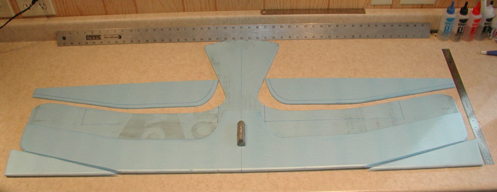
[Above]: Initial layout is done using the fold between two panels of Bluecor as the leading edge. Span is 48", Chord is 8". The tip half (12") of each wing is swept back 3" at the leading edge. A cutting mat is then slipped between the bluecor layers to do the upper layer cut at 50% of chord. You can see that the ailerons are laid out, 16" long with a minimum width of 1.5".
Also, the spacer strips that will go between the bottom and top wing layers are marked on the cut-away pieces, ready for cutting. The remainder of the cutaway pieces could still be cut again to add a secondary step at ~70% of chord, similar to what was done on the third DANCER wing prototype. (That wing has proven to be the most efficient of the three wings for slow speed thermal gliding performance to date.) This wing's airfoil will be just under 9% thick at the step / thickest area.
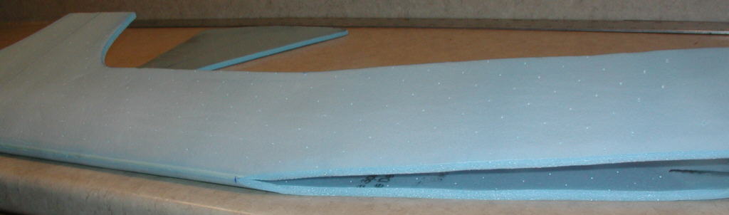
[Above]: Next, the upper surface portion of the wing was rolled over a 4" diameter tube to start shaping the curvature for the upper wing surface.
[Above]: The spacer strips are ready to be glued to the edges of the upper wing surface. I used foam-safe CyA glue for this.
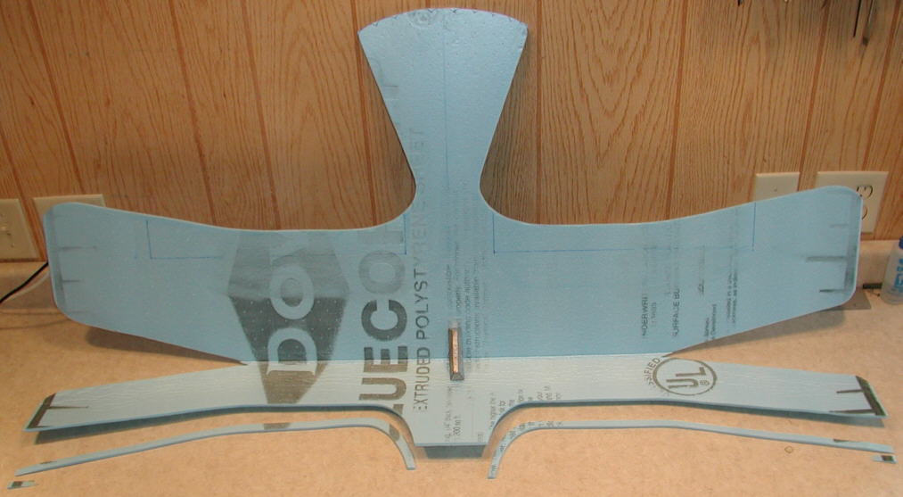
[Above]: The trailing edges of the wing and ailerons have been extensively heat-formed / thinned in this photo. The elevator has been cut and tape-hinged. The 1mm diameter x 36" long C.F. rod cap spars have their rounded depressions formed & 'wood-peckered', ready for gluing the spar caps in place on the top and the bottom surfaces. These are located at 40% of wing chord, relative to the inboard wing panels.
In a manner similar to the DANCER wings, these wing tips will be upswept somewhat and further shaped to a 'feathered' tip profile as the build process progresses. These upswept wing tips perform two valuable functions; they provide some flight stability similar to conventional dihedral, and they effectively move the wing tip vortexes up away from the outer wing panel's surface, allowing more of the wing surface to generate more lift.
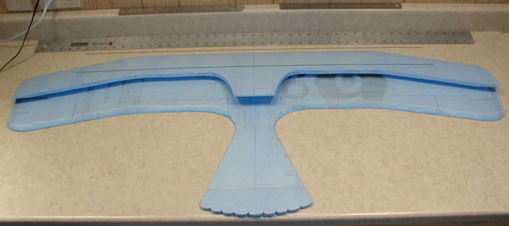
SOARBIRD4 was not performing in it's HLG mode, and it was not easy deciding what it wanted. I fad played with tailgroup modifications, adding more vertical stabilizer surface area, but it still was not gliding well. So I finally decided to get a bit ruthless, and did a chop job on it. I reduced it to just being a wing which I could mount on a separate fuselage for the next stage of testing. The result, at this point, is what you see in the photo.
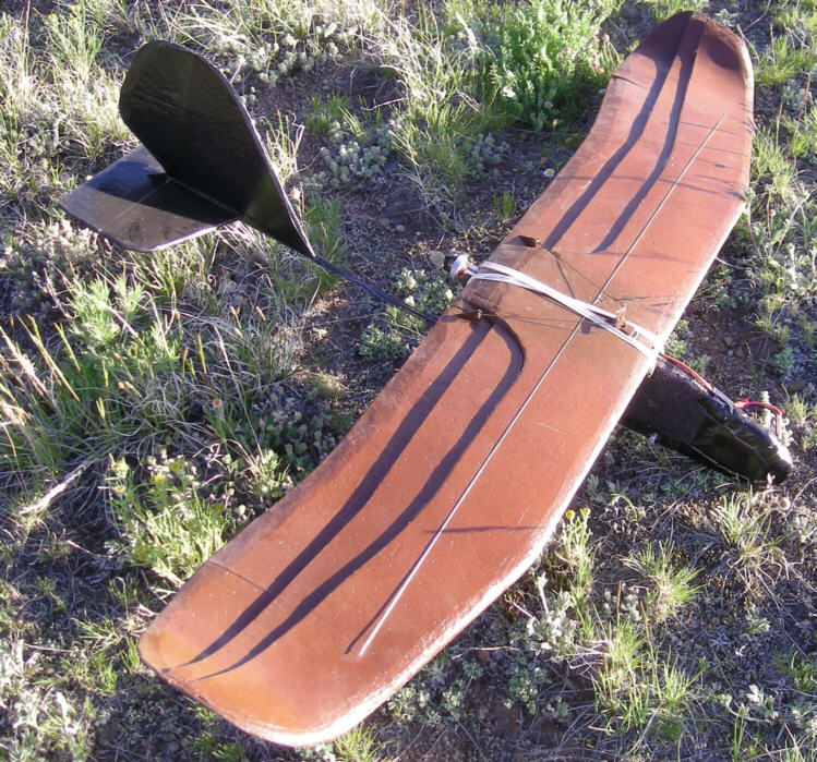
Above: Soarbird4 was chopped down to just the wing in order to do flight evaluation with it mounted on the Slim Beagle fuselage. It's a fun aerobatic glider wing, highly responsive, but has more drag than I want; wing tips may benefit from thinning.
I then started playing with wing / tailgroup incidence adjustments and balance shifting to get it flying as well as it could.
The good: this wing, when mounted on the "Slim Beagle" fuselage, is a decent aerobatic fun fly wing. It has very good aileron response, as well as good response to turning with rudder only.
The bad: this wing is not as efficient at power-off gliding as the Dancer series of wings, and especially rates poorer in comparison to the Me163-e Komet's wing design. Why? My theory at this point is that the three layer airfoil is a bit too thick, possibly at the leading edge, and especially at the wing tips. (The wing tips were built heavier to make them more durable for rough field landings, but in retrospect, that was a poor trade.)
To do as well as it could, this type of wing would need to be re-profiled into a thinner airfoil with more shaping / contouring of the forward 25% of the chord. Wing to H. Stab. incidence is also critical for this type of wing to glide efficiently.
What's next? I'll likely take the fillet knife & sanding blocks to the wing tips, thinning the extra layers to merge into only the single layer thickness for most of the upswept wing tip sections. This should reduce drag noticably- at least, that's what I'm expecting at this point. So the prototype of SOARBIRD4 has morphed into a test wing, and will go through further changes.
Here's a photo of the results after carving away the extra two layers of Bluecor PP from the wing tips. (The exposed area was then quickly covered with a layer of black packaging tape before the flight test.)
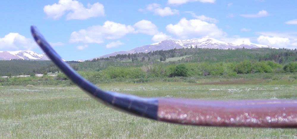
Above: Results after the extra two layers of Bluecor PP were carved away from the upswept portion of the wing tips. The improvement in both glide efficiency and flight stabiliy are nothing short of amazing!
How did it work? Beyond expectations!!!
Drag is reduced dramaticly- more than I had guessed it would be. And as an extra bonus, the flight stability also improved dramaticly! It's like an entirely different wing! The power-off glide efficiency has now improved so that it may be close to comparable to the Dancer's ~8.5% thick wing- it's come a loooooong way- simply by removing the excess layers where they did NOT need to be, in the wing tips.
Elevator trim setting is still sensitive for best glide efficiency, and fine-tuning the CG / balance point closely will also always be important for achieving the best possible glide efficiency. Right now, this wing on this fuselage is a pleasure to fly!
The next step is to take this modified wing design and redesign how it mounts into a new fuselage with an effective tail group. A full flying tail is the main design option which I'm considering implementing; it would allow trimming for most efficient glide, and offer very good control authority. A operational rudder will also be considered. I can then also add back in some of the wing feather detail, to enhance the bird-like silhouette against the sky when it's flying. I'll post updates here when time allows me to return to this project.