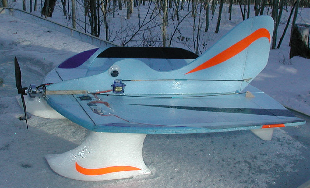

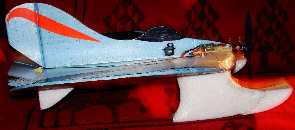
Here's a new KF'ed snow flyer which I just completed & test-flew in late December as the new snow storm was beginning to put down more fresh snow at dusk.
You can tell just by looking at this cute li'l girl that she has influences from her cousins, The HOOT, the Nutball and the Snowball... but she has a definite cute 'cartoonish' look to her upper body, her wobbly eyes, and her stylized solid EPP skis.
The back quarters were morphed wider on the 20" disc to add an extra ~16 square inches of surface area, for 2.29 square feet total. With a flying weight (after the colored trim was added) when flying on these EPP skis of only 7.75 ounces, the wing loading is only 3.38 ounces per square foot.
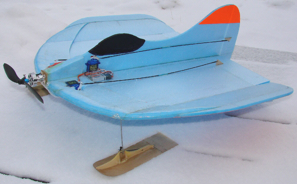
What this 20" FLIRT was designed to do is to fly in a much smaller sapce that what I'm comfortable with when flying my larger & heavier T-tail Snowball, and at only 7.75 ounces flying weight, it's ideal for that. I can fly in the tree-lined road just at the end of my driveway, take off & land is narrow slots between potentilla bushes, and fly very slow high alpha maneuvers with this light girl. She simply loves to flirt with the snow, the trees, & the bushes- a really playful light flier that's still plenty tough enough to deal with less than ideal envitronments. She's a great compliment to her big brother.
The 1-1/4" wide EPP skis are working fine from older snow- she's light on her feet; we'll see whether new soft powder snow will necessitate adding a modest set of 'Bigfoot Overshoes' , like I have for occasional use on my larger T-tail Snowball. (It's simple to tape them in place, & remove them when they are not needed- just like overshoes are supposed to work.)
With such tall skis adding this much area up front, and with only the rudder & elevator, it rolls much better to the left than to the right... but I built this one for flying low & slow in tighter flying areas, and to handle predictable for a novice flyer I'm teaching, and it is performing well for that. It does some high-alpha flying at slow speeds very nicely, can take off from the firmer snow in about 8 feet, and turns tightly in a very small amount of space. It flies at 1/3 trottle well, has far more power than it really needs, in is a fun flier.
Having skis added to a 20" '___ball' variant with only 3/4 ounces of weight gain is kinda nifty! And since these EPP skis are completely covered, and then mounted to the wing with the 3 mil DocuLam laminating film, they are not only tough and waterproof, but they can optionally be taken off after snow flying season so that wheel gear can optionally be mounted for flying our Rocky High Country. (No sod farms around here...)
The wing was built with an added narrow eliptically contoured top doubler panel and has a well-shaped leading edge. The result is that there is none of the pitch sensitivity which a flat plate wing can exhibit, and it is capable of handling full-throttle flight smoothly and predictably. This top KF variant panel extends only 3.5" back, which is 17.5% of the total wing disc. And it's doing exactly what I wanted it to do for the leading edge dynamics, without adding too much weight from extra doubler area that's really not needed for this application. (My Skyray F4D was the first to be built with a narrow eliptical top doubler panel, and it's also working superbly.)
Here is an AVI format video of the FLIRT flying from hard wind-carved snow and ice; it's a 36MB file. In order to view it without pauses, it may be best to right-click on this link, and tell your system to save it to somewhere on your local computer. Once the download is completed, you can watch it uninterupted. This is an unedited video 1:03 minutes long, shot with a helmet cam setup. It will give you an idea of how well the FLIRT 20 handles these rough surfaces, shows a bit of how smothly and quickly it rolls, as well as showing how well it handles at slow speeds and landings. Right-Click here to save the FLIRT397.AVI video file for viewing
Get out and FLY IN THE SNOW!!!
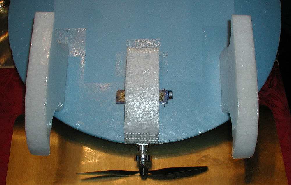
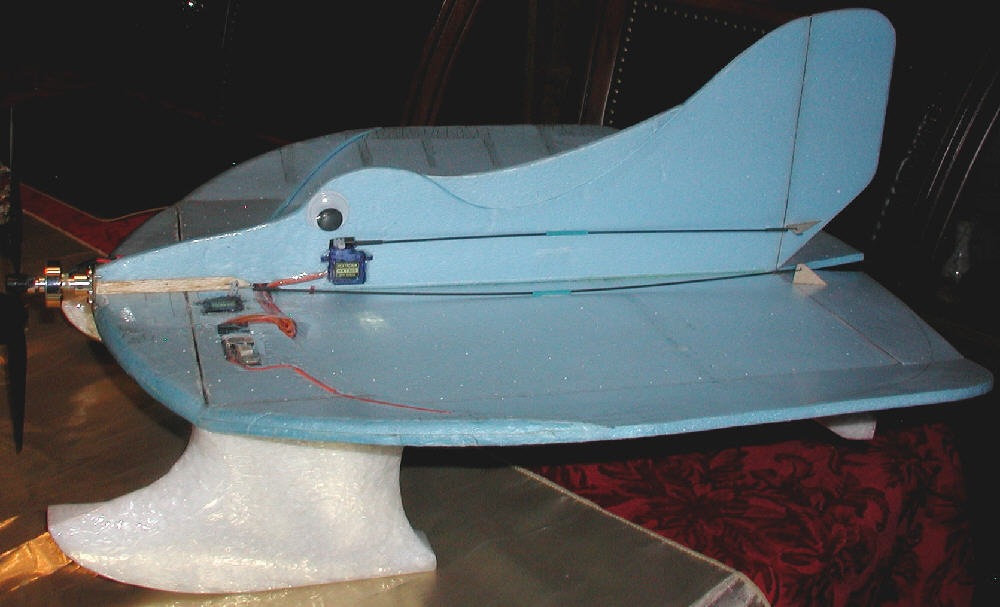
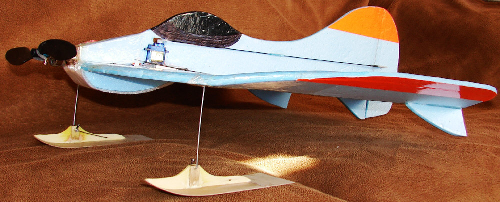
Above: The 20" Bluecor PP FLIRT sits on a pair of 1-1/4" wide skis, designed for snow flying
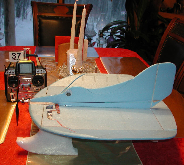
Above & Below : The EPP skis extend back far enough to support the aircraft without having the tail drop
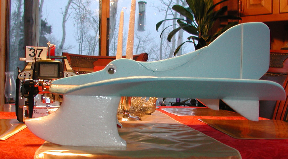
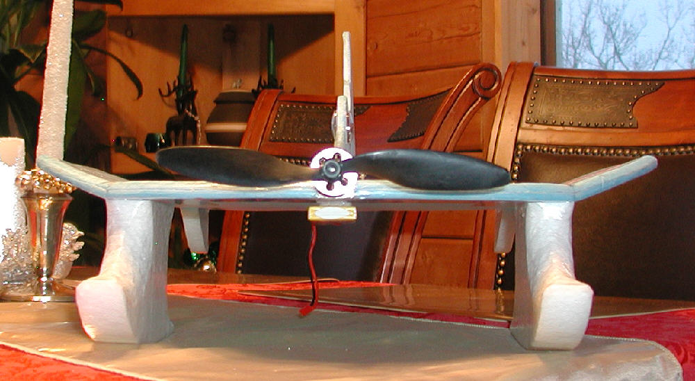
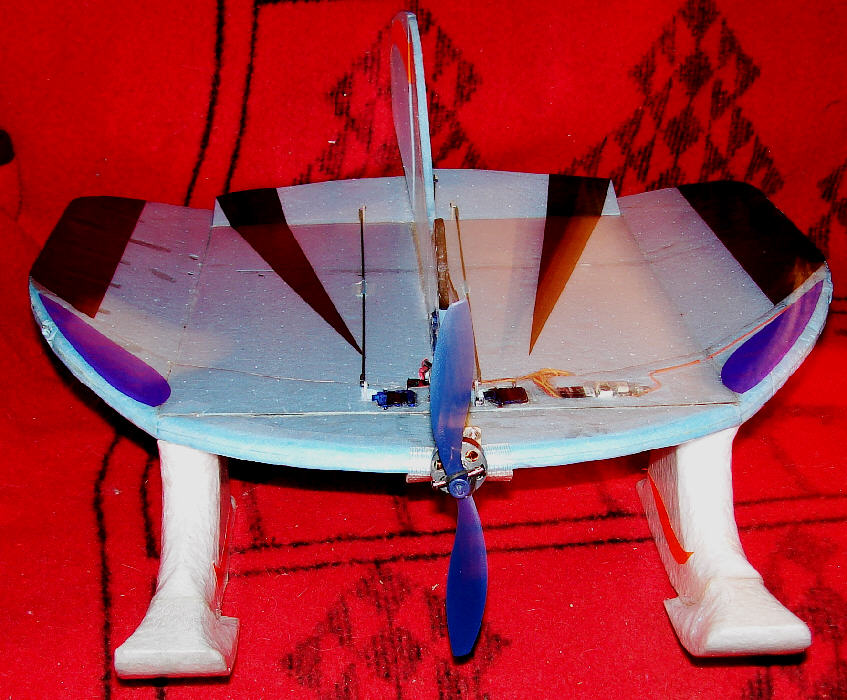
Above: The wide ski stance gives excellent ground handling stability
Wingspan & Length: 20" (Disc with rear quarters expanded somewhat)
Panel widths: 12" center width, 4" tip panel width
Dehedral Angle = 19 degrees up for each tip panel
Wing Area: 330 square Inches = 2.29 Square Feet
Final weight after decorative trim, without battery = 6-5/8 Oz.
Flying weight with the EPP floats mounted, with the 2S 460 mAH battery= 7.75 ounces
Wing Loading : 3.38 Ounces per square foot with the floats mounted, and the elevon function enabled
Starting C.G. 5" back from front center of wing = 25% of total disc length
Elevator Span: 12" x 2-3/4" maximum chord at center; (later split at center to use as elevons)
Rudder max. height 6.9"
Materials Of Construction: Bluecor PP and EPP skis and tail skids
2mm solid CF rod stiffener used span-wise on top surface 2" back from L.E.
1.5mm CF rods used for elevator and rudder control rods with .032 music wire ends
Motor Used: C20 1500Kv Brushless Outrunner: 20 grams
ESC : MAG 8, 12Amp
Battery: 2S 460 mAH Rhino LiPoly
Propeller: APC 8x4.3 SF used for first flights ( Optional: APC 7x5E for more clearance in deeper soft snow.)
Radio Receiver: Corona RS410 II Four Channel micro Rx with base loaded antenna modification
Transmitter Used: Airtronics RD8000
Servos: two HXT500 for elevator and rudder (Later added a third servo to implement elevon control)
Optional Floats: 1.3# density solid EPP; ~7.8" L. x 3.8" H. x1.25" wide; 3 mil laminating film covering (3/4 ounce for the pair)
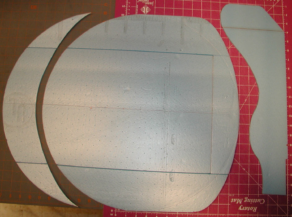
Above: Cutting out the 20" FLIRT, with the eliptical top front KF variant panel
I used Bluecor PP for building the FLIRT. Other types of fanfold foam or Depron could also be used. The Bluecor has far less flexibility than EPP sheet, so it offers good rigidity without requiring much in the way of stiffeners and structural reinforcement. Once the top front doubler panel is added, the wing's leading edge area is quite strong. It can then be carved, sanded, then heat-tempered and contoured to a rounded airfoil-shaped leading edge shape.
These are the progressive steps of the main wing build:
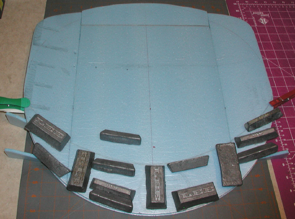
[B]Marking & Cutting The Wing Panels.[/B] I set a center pivot pin through the foam into a wood backing piece that the pin will hold in well, at a little over 10" from two edges of the sheet of foam. I then take a piece of soft wire or string and make two loops in it 10" apart. With one of the loops over the center pivot pin, I insert the tip of a fine-point Sharpie pen through the other loop and draw the circle while holding mild tension against the center pivot pin.
I use a 'French Curve' to draw the added areas at the rear corners, and to draw the trailing edge cut line for the narrow top doubler panel. These steps allow a bit of 'artistic license' - The contours I used do work well on the FLIRT which I am flying. I also draw the center line, front to back, for use in aligning everything.
[B]Make FOUR 19 Degree wedges from scrap foam for setting the fold angles while glueing[/B] I use a protractor to mark and cut a set of four wedges at a 19 degree angle. These can be quickly set in place under the folded wing tip panels when checking the wedge slots you make where the wings fold, and when gluing to set the identical angle on both wing tip panels.
[B]Cutting The fold slots in the main wing panel[/B] I use an adjustable temperature soldering iron with a narrow pointed tip to melt a slot ~90% of the way through from the top surface of the foam. I set the soldering iron's temperature just hot enough to melt a clean slot without melting extra foam. I test on scrap foam to get the temperature setting right. I use a wheel collar in the soldering iron tip to control the depth of the melted slot, and have the wheel color running along the edge of a metal straight-edge or yard stick. Cutting these fold slots can also be done with a sharp knife blade; the idea is to leave the lower surface film intact, while removing enough foam so that the wing tip panel can fold up to the desired angle. Use the 18-19 degree wedges to check the angle of the foam, & adjust the fold slots as needed.
[B]Cutting & hinging the elevator / elevons[/B] I find that it's easier to cut away the elevator / elevons, bevel the hinge line edges, and then tape-hinge them back in place before proceeding with the rest of the wing build. I use Scotch brand Transparent Multi-purpose tape for hinging; some prefer other tape for hinging. I weight down the two pieces to be tape hinged with a 1/32" gap between (to allow room for the underside hinging tape to fold in the gap without binding the hinge.) I hinge the top surface first, trim away excess tape, then fold back the control surface and add the hinging tape to the underside of the hinge line.
[B]Glueing the fold slots in lower panel;[/B] I use hot-melt glue for this- it sets fast & holds well for this joint. After test-fitting the fold slots with the 19 dgree wedges, hold open one wing fold slot and quickly apply the hot melt glue . Then quickly fold the joint up and weight down the main flat center panel on a flat surface while two of the angle wedges are slid in place to support the tip panel at the proper angle while the hot-melt glue cools & sets. Once the first fold is glued & it's glue is cooled, you can do the same with the other side.
[B]Cutting the fold slots in the upper panel[/B]- I find that it works best to cut the the upper panel fold slots a bit narrower / closer together than the lower panel, so that whe folded, it will lay well on top of the main wing panel. Do the fold slots at the same angle as the main wing was done. Gluethe fold slots on the upper panel while it's still separate from the lower panel, using the 19 degree wedges.
[B]Glueing the panels together[/B]: I prefer to use a light coat of 5 minute epoxy for this job- it sets up fairly fast, but not too quickly. After test-fitting to verify that the panels fit together well, I mix & apply the thin coat of epoxy to the lower wing panel, and then weight down the upper panel thoroughly, with two of the 19 degree wedges in place supporting each raised wing tip panel. I add weights to keep the panels closely mated while the epoxy sets up.(The top panel was actually set back 3/32" from the main panel to start the leading edge contouring process; later, carving with a razor knife was done before the heat-shaping and tempering of the foam was finished with a covering iron.)
Above: After cutting the lines 90% through where the wing tip panels would be folded up with an adjustable temperature soldering iron, the dihedral joints were glued with hot-melt glue and the angles set with four 19 degree wedges made from scrap Bluecor. Once the dihedral angles / joints were set on the main wing panel, the top front narrow eliptical KF variant panel was also set to the dihedral angles, then glued to the main wing panel with 5 minute epoxy glue.
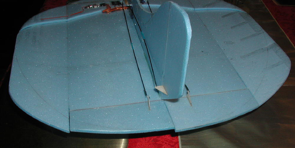
Above: Vertical fuselage being held in alignment while the 5 minute epoxy sets up.
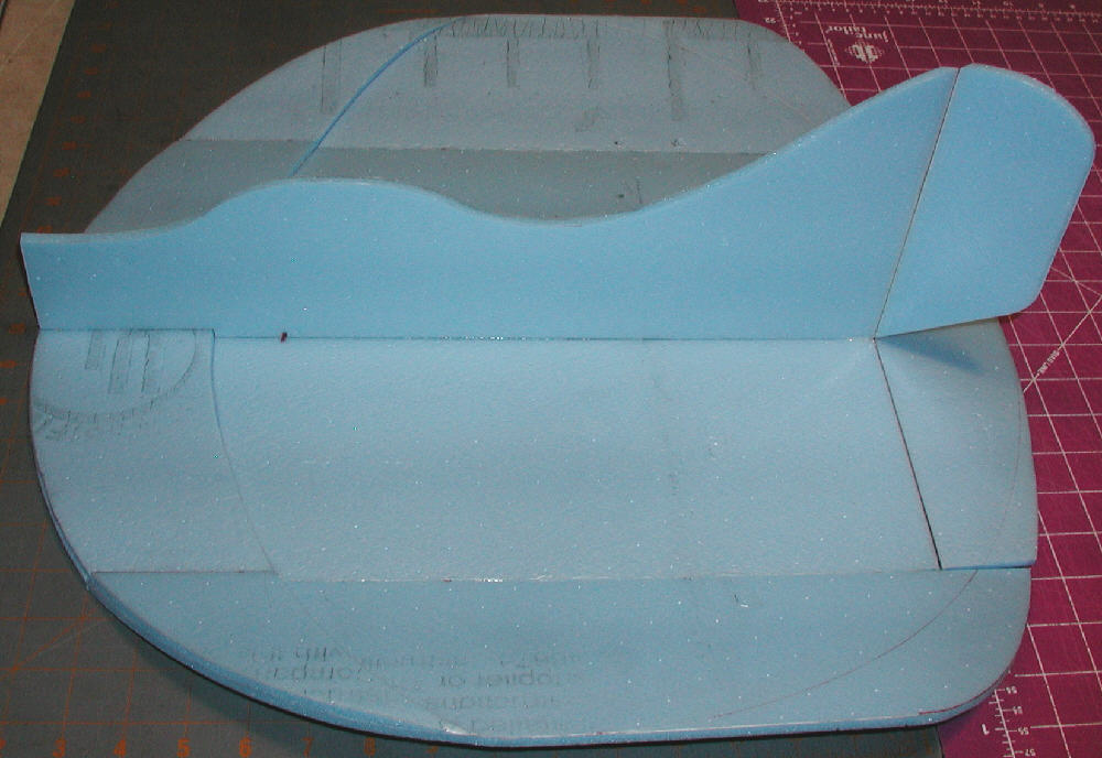
Above: Foam was cut oversize for the first prototype of the upper fuselage, offering the possibility of mounting the motor well above the wing so that shorter landing gear or lower profile skis might be used. I then chose next to cut down some of the extra upper fuselage foam, and to mount the motor just above the center line of the wing, since I firmed up my plans to use the taller profile EPP skis.
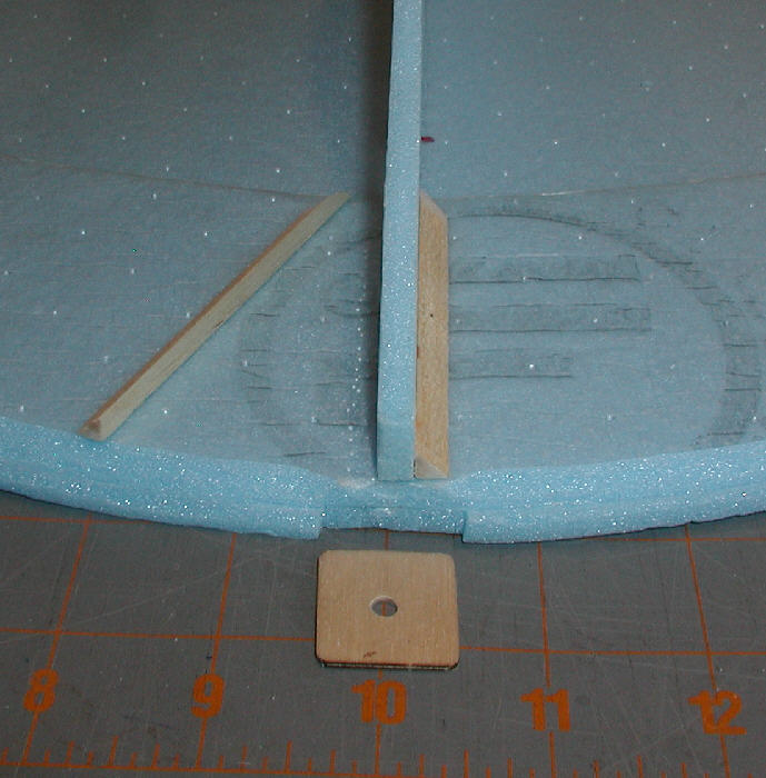
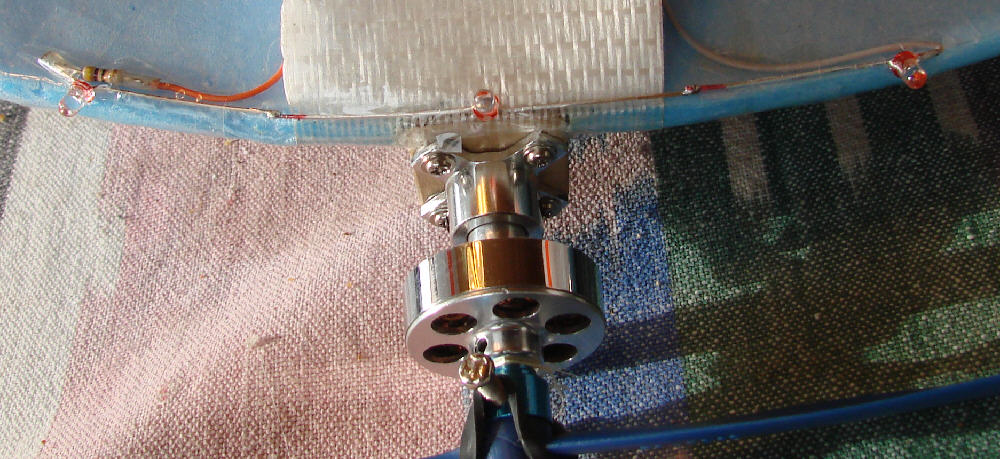
Above: Motor mounting simplified; a ~1" square piece of 1/16" birch aircraft plywood is the motor mount firewall; two pieces of firm balsa 1/4" triangle stock distribute the loads back into the airframe. 5 minuute epoxy bonds everything together. This is plenty solid for a 7 ounce aircraft's motor mount system!
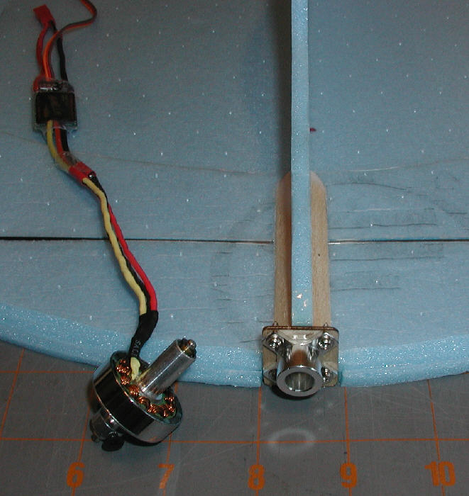
Above: C20 1500Kv motor ready for testing, and it's firewall mount in place with four servo screws. (I used a dremel tool to open up the center hole in the firewall further to be sure to clear the rear end of the motor shaft nicely.)
Above: Before the motor mount was epoxied in place, a 2mm CF rod stiffener was installed across the wing 2" ack from the center front; A groove was first cut with an adjustable temperature soldering iron so that the CF rod would sit inset flush with the surface. It was glued in place with foam-safe CyA glue.
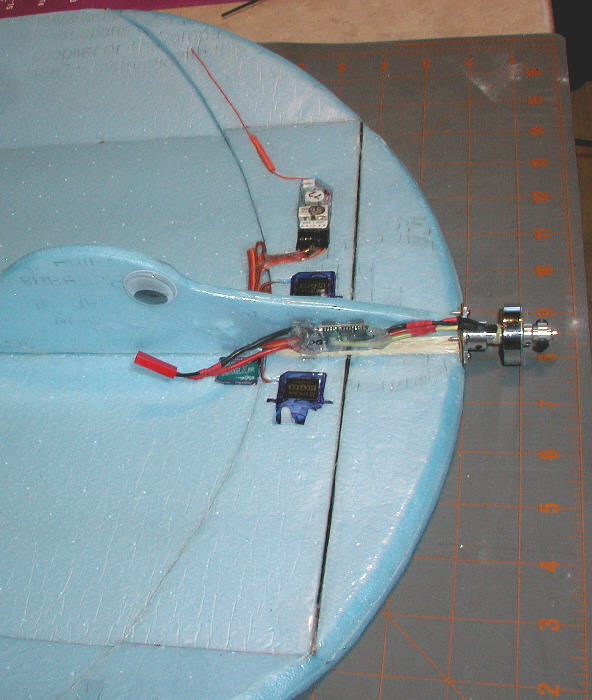
Next, the servos were inset within the two layers of Bluecor PP, and the Corona radio receiver was also inset into a recess cut into the upper layer of the double thickness foam. The Receiver's antenna was modified into a 'base loaded coil' shortened configuration. (I'm flying this modified antenna setup successfully on about a dozen aircraft or more at this time- it works great!)
The motor leads were shortened extensively, as were the ESC's motor leads, to eliminate a lot of excess wire and keep the ESC well forward. I then lashed down the motor wires to the motor bearing tube with some kevlar thread wraps and thin CyA glue to keep them from moving and thereby getting broken.
I am flying the base loaded antennas on a lot of aircraft that fly out to well over 600 feet away, and they perform superbly; I'm doing this modification on the Corona RS 410 II receivers. What we are doing is forming an air core 'base-loading' coil with nothing other than the antenna wire itself wrapped around a 3/32" O.D. coil form tube. In this case, the K.I.S.S. approach works very nicely!
You do not need to buy anything from anyone, you only need a small diameter plastic tube, about 3/32" O.D., and a larger diameter needle to make a couple of holes in the right places.
The process is simple; take the entire (~39-1/4" length) antenna, fold it in half to identify the mid-point, and cut it there; you now have just under 20" of antenna wire.
Next, use a sharpie pen to mark a spot 2" out the wire from where the wire is soldered to the receiver circuit board; mark another spot 3" back in from the outer end.
Start with about 2" of the ~3/32" O.D. plastic tube, poke a hole with the fat needle about 1/4" from one end. Then thead the end of the antenna wire in through the end of the tube and out through this hole. Draw the antenna wire through until the mark which you made 2" from the receiver is just at the pinhole.
Next, wrap the antenna wire around the tube with the wraps tight against each other; wrap until you get to where the mark is at ~3" from the end of the antenna. Kepping the coils tight, make another hole with your fat needle where the antenna wire will be run into the interior of the tube & out the outer end; (do this close to the end of the coiled wraps so that they will stay tight together once the entire process is completed). Trim away excess length of the plastic tube about 1/4" beyond the second needle hole. Then insert the end of the antenna wire through the needle hole & out through the end of the tube and snug down all of the wraps.
That's it!
Try to route the antenna so it's not running close & parallel to metal control rods or carbon fiber rods & tubes if you can. The C.F. may not be an issue, but metal control rods can possibly be of a harmonic length in relation to the antenna which can possibly absorb some of the signal.
If you are interested, you can do your antenna-down transmitter range check before and after doing this antenna modofication, so you can get an idea if there is any significant range reduction; I am using it on over a dozen different aircraft now without any glitches or signs of signal loss.
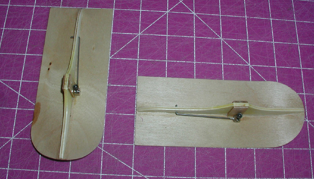
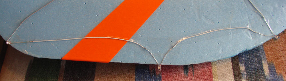
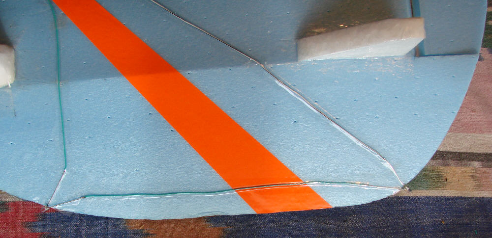
Above: Control rods are made from 1.5mm solid C.F. rods with .032 music wire ends with Z-bends. A plastic guide tube is used in the center of each control rod run to eliminate any flexing; guide tubes are glued to the Bluecor.
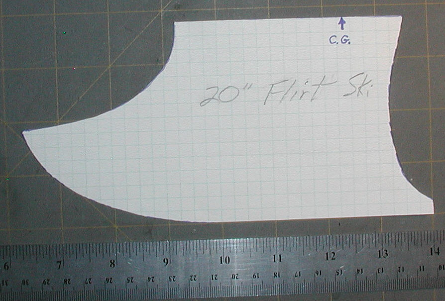
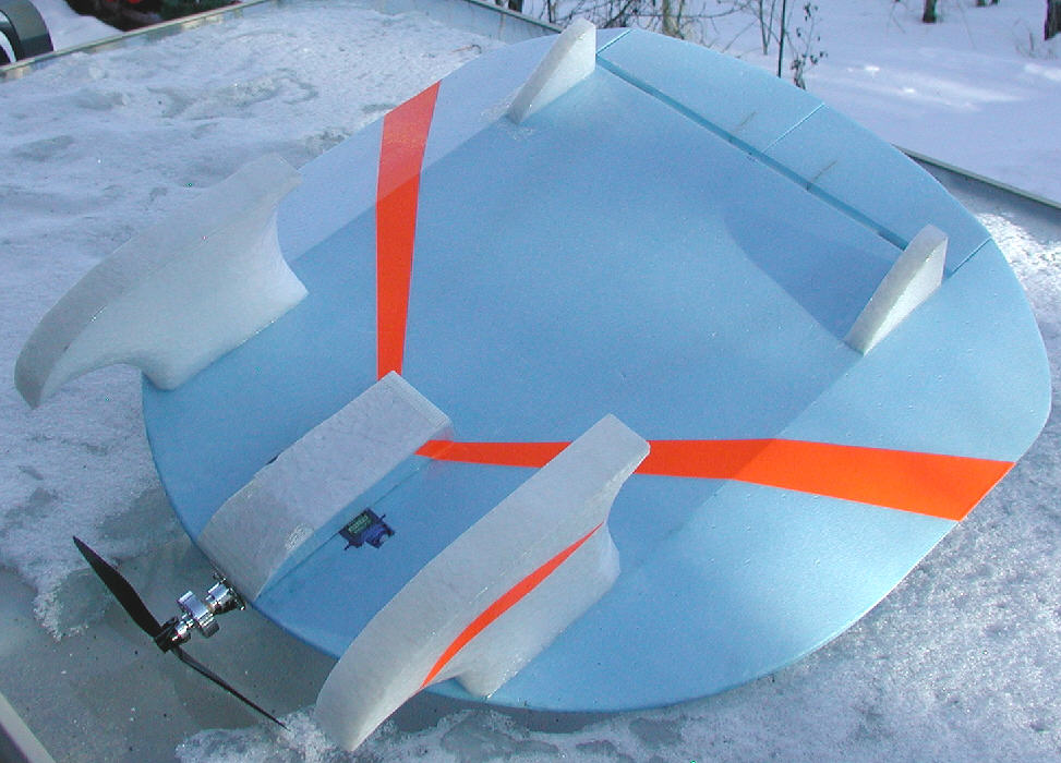
Above: This is the patern for the EPP floats that I made for the FLIRT
I've flown a LOT of different aircraft from snow over the last ~25 years, with a variety of floats and skis mounted under them in a variety of ways. Most of the earlier skis that held up well over years of use were made from Birch aircraft plywood of various sizes & thicknesses, mounted on Music wire landing gear. These ski setups were solid and reliable, but added a fair amount of weight to the aircraft. And I developed the torque rod systems of fastening the skis in position on the axles so that they would not rotate out of alignment through all of the takeoff, flying, and landing stresses... (Landing with a ski tip pointed down was always an unsettling experience...):eek::rolleyes:
Woodstok, designed in ~2007, was the first design on which I used solid EPP Floats which also served well as skis. To get even better handling while flying from water with a modest amount of power, I added the triangular hard balsa 'chine' rails to the outside edges of the bottom of these floats. Woodstok with his floats is going into his fourth season of winter flying, and the flaots are still holding up fine!
The T-ball variant inspired by the Snowball design is working great flying from either water or snow on it's solid EPP foam float/skis; I had added some side-cut to the shape of these 12" long floats when designing them, to have them get up on top of the water very cleanly and quickly.
The Voyager is the third design shown below, which has 24" long EPP floats. The wing structure was designed & built so that these floats could be mounted directly into the wing structure without using any heavy music wire mounting strut system.
For the flirt, I wanted to keep weight to a minimum while having a tough and durable ski setup. (I was not designing these EPP skis for water flying at the time, although they may also handle well from water, too.) I started with a scrap block of 1.3# density EPP, laid out the bottom contour, then decided on the height that would rusult in adequate prop to snow clearance. Since the block of foam which I started with was ~2.5" thick, I ended up with a pair of skis at ~1-1/4" wide.
Over 20+ years of ski flying, I've developed a preference for ski setups which carry the weight of the entire aircraft, and keep the tail up out of the snow when sitting at rest. These handle best through a variety of snow conditions. So the tail ends of the FLIRT's skis were designed with the tail end of the skis well behind the C.G. of the aircraft. The wide spacing / stance of this ski setup also gives it incredible stability for irreverent antics on the snow- ideal for a lot of fun in the white stuff that blankets the high country for so many months of the year.
The FLIRT's elevator / elevons and rudder are large enough to lift the tail and turn this fun flier around in tight circles on the ground when desired. Adding some up elevator and power will drop the tail, allowing it to have a positive angle of attack to ROG from snow in only 8 to 10 feet. At 7-3/4 ounces, this aircraft is light & nimble on it's skis, yet in the air, it handles winds very well- a nice combination of capabilities
The floats were then cut out, carved to give a bit of aerodynamic streamlining, then covered with 3 mil 'DocuLam' laminating film. The film was left extended about 3/8" above the edges of the upper mounting surface (with overlaps forming two layers on the bottom ski running surface). After covering was complete, and the mounting area on the underside of the wing was overlaid with a layer of the laminating film too, the skis were each positioned and held in place on the bottom of the wing while the 3/8" wide flaps of laminating film were ironed onto the wing's lower surface. This is enough to hold the skis in position; in this way they are easily removable so that wheel gear might be mounted later, yet the laminating film is so tough that they are held very solidly in place.
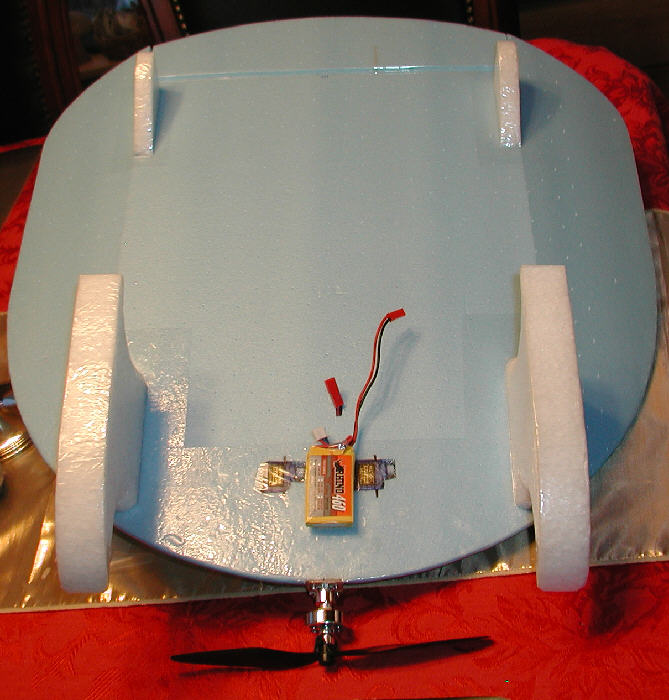
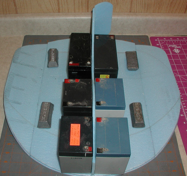
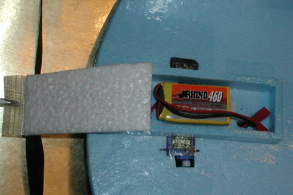
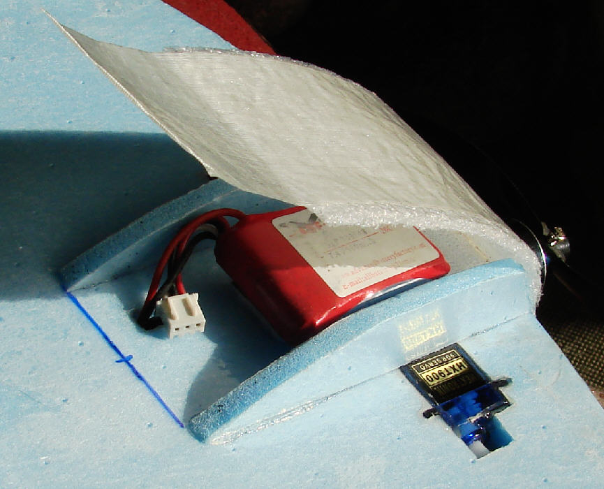
Above: For the first test flight, the 2S 460 mAH battery pack is mounted on velcro on the underside of the wing, as shown, to balance the aircraft at the proper C.G. (Starting C.G. is good at 5" back from the center leading edge of the wing- 25% of total wing length.)
I know that there's a lot of indoor flying done in the winter by some fliers. Many of us don't have access to indoor flying sites, so we are sorta 'left out in the cold'... but that's OK- snow flying is really a lot of fun, too!
With temperatures in the single digits this A.M., and a few more colder nights promised, I'm thinking that it's going to be a good idea to see about keeping the battery from chilling too much on the new FLIRT 20 Nutball variant. (GPW has even commented in the past on batteries loosing performance as the temperature goes below 40 degrees... we do a lot of snow flying up here at temperatures well below that, so it's something we simply plan to deal with.
On my SNOWBALL, the battery fits snugly into a compartment in the lower part of the EPP motor mount block, with a thin foam side cover that simply tapes in place for colder weather flying, and that works well. On this one, I'm thinking of making a compact battery compartment on the wing's underside that can enclose the battery, while having some room to allow for flying a larger (2S 900 mAH?) battery, or to shift the velcro-mounted battery a bit forward to adjust the C.G.
I'll be working on adding the battery enclosure compartment soon.
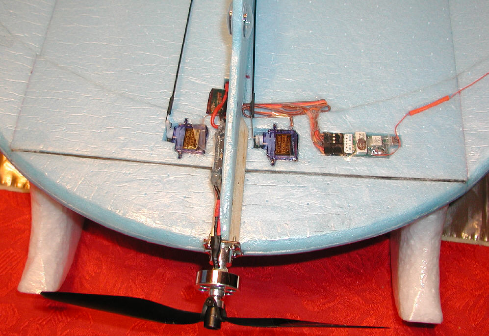
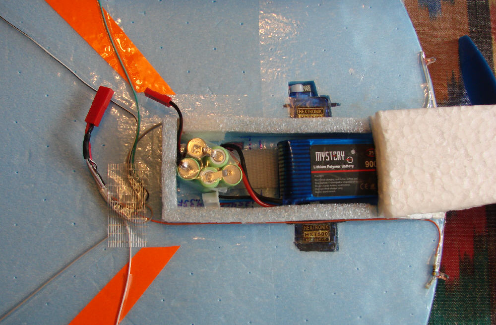
Above: This is a closer look at the power system & radio gear installation. I am flying first flights with a GWS 8043 SF prop; I may switch to an APC 7x5 E prop to gain another 1/2" of prop clearance when flying deeper soft snow.
The battery compartment is now completed.
I was also thinking of how well the elevons perform on the HOOT, which also has narrow wing tip panels which are angled up from the main wing panel. That aircraft started life with elevons only, and gained the rudder later; the rudder increased it's maneuverability nicely!
So I decided to try an experiment on this FLIRT 20, by adding elevon control, to see how the roll response would be. I split the elevator in the center to form two elevons. I installed another HXT500 servo to take over the rudder control function, and set up the origional two servos to control the elevon function. Flying weight (with the 2S 460 mAH battery) is now up to 7.5 ounces after these additions. The photos below tell the rest of the story. I'll report on the next test flights once the bitter cold and very windy weather improves.
Even though the temperature never climbed above ~14 degrees today, the wind started to mellow by afternoon. So I decided it was time to do some flying of the FLIRT 20 now that the Elevon control setup had been implemented. I had removed the extra add-in stabilizer panel just in front of the vertical stabilizer, too.I had also added the fluorescent orange trim tape to the underside to help maintain visual orientation.
For this quick test flight, I just walked out to the end of my driveway and hand-launched it by letting it fly up & away out of my hand with a gentle toss in a nose-up attitude. It climbed out smoothly in the moderate winds; I gave it some elevator trim, then started to put it through it's paces.
I'm happy to say that the elevons are very effective, giving a smooth almost-axial roll in either direction, left or right, at roughly the same rate. It's now also easy to roll it inverted and hold it there. It does smooth outside as well as inside loops. The rudder is still the same as before the elevons were enabled, still quite effective, too. The FLIRT 20 is now far more capable than it had been without the elevons, and it's flying very predictably. (The experimental vertical stabilizer filler panel that had bee installed and test-flown was removed again- it does not need it.) It's handling winds very well, and with the elevons, it can deal with cross-wind gusts on takeoffs & landings more easily. I'm looking forward to being able to fly it in some calm air conditions some day soon.
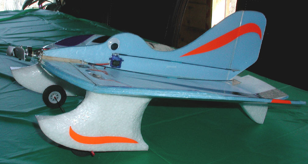
The rest of the decorative trim, done with colored packaging tape, was added after this test flight. The final flying weight as shown in these three photos below is now 7.75 ounces when flying with the 2S 460 Rhino LiPoly battery pack; that comes out to a wing loading of 3.38 ounces per square foot.
No further changes to the airframe are anticipated at this time- it's now a real sweetheart of a flier!
The decorative trim work has been added now that all of the airfraim & setup adjustments are completed. (The FLIRT 20 is also an excelent candidate for an LED night flying setup- it handles very well, so would make a good night flyer.
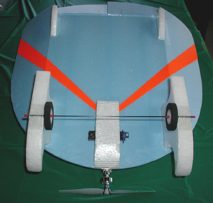
Above & Below: What do you do between snow storms with a FLIRT on EPP Skis? That's easy! - Just tape on a 2mm C.F. rod axle with a pair of wheels, and go Flirt with the dirt!! Pieces of stripped 18 Ga. wire insulation are a snug fit on the axle, and act as great wheel locators. I use the Scotch 'Extreme' Cross-filament nylon filament tape to tape this axle across the bottoms of the floats. When snow covers the area again, the tape can be quiclky peeled away in far less than a minute, and the FLIRT will be ready to play in the snow again!
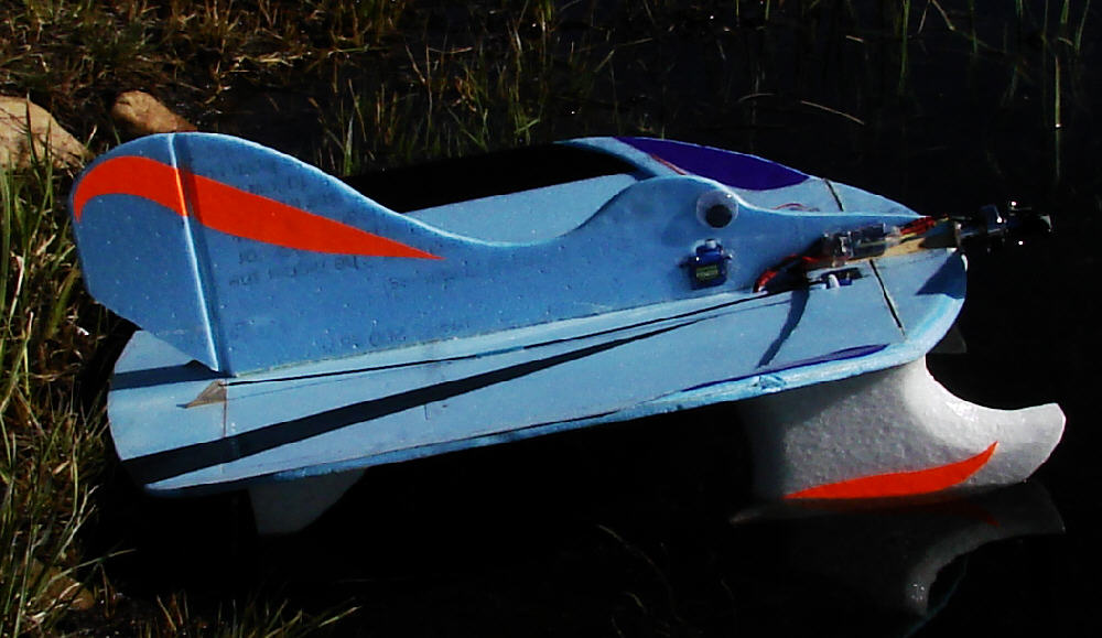
I had built these front ski / floats for snow flying last winter, and while the Snowball's longer floats do handle very well from water, these ones are also working decently from water. I did several takeoffs and landings from water this morning with no problems. (I have now switched to an APC 7x5E prop for better prop to water clearance, and by holding in some up elevator when starting the takeoff ROW run, the FLIRT20 gets up & off the water within about 12 feet.) It lands very predictably, and can be landed at ridiculously slow speeds if desired.
With a wing loading of about 3.5 ounces per square foot when flying with the heavier 2S 900 mAH battery pack, the FLIRT20 is certainly not anybody's idea of a 'windy day flier'... but it handled light winds fine on the water today. The wide stance on the floats certainly helps in the stability department! (Both the Snowball T-Tail and the Voyager have a fairly wide stance to their float mounting setups, too, which helps in dealing with side-wind water taxiing situations without problems.)
Float / Ski Modifications
The FLIRT's EPP skis, as initially cut, worked out OK for flying from both snow & water, but I had times last winter while snow flying when I was thinking that the skis would perform better in soft snow if they were wider, and would also perform better if they extended farther in front of the prop's arc. (The handling while taking off from water should also be improved by these modifications.)
With more snow falling up here in Colorado's high country, I decided it was finally time to cut some add-on EPP front extensions for the EPP float / skis. I started with a leftover block of 1.3# density EPP which was 2" wide. I marked & cut the foam (on my band saw) to match the original float/ski's forward curved contour, extending the ski by 2-1/4".
I then attached these extensions to the existing floats with hot-melt glue, and carved away some excess foam to get a more flowing contour the the upper sides. I then ironed on some clear covering film (Doculam) to waterproof these float/ski extensions and give them a slick running surface. Last, the float/skis were reinstalled on the underside of the FLIRT's wing.
The result is what you see in the photos. Airframe total weight is 7 Oz without the battery; with a 2S 460 battery, the flying weight is at 8 ounces, for a wing loading of 3.5 ounces per square foot. It now balances for flying with the battery about 1-1/4" to the rear of where it mounts when flying without the float/skis, still within the battery compartment.
For flying in some wind, I like to use a bit larger / heavier battery. With a 2S 900 Mystery battery installed, flying weight comes up to 8-5/8 ounces, bringing the wing loading up to 3.75 ounces per square foot... that's still pretty light. Balancing still works well OK the larger battery mounted to the rear of the enclosed battery compartment. (Keeping the battery warm really is critical to maintain battery performance when flying in cold weather!)
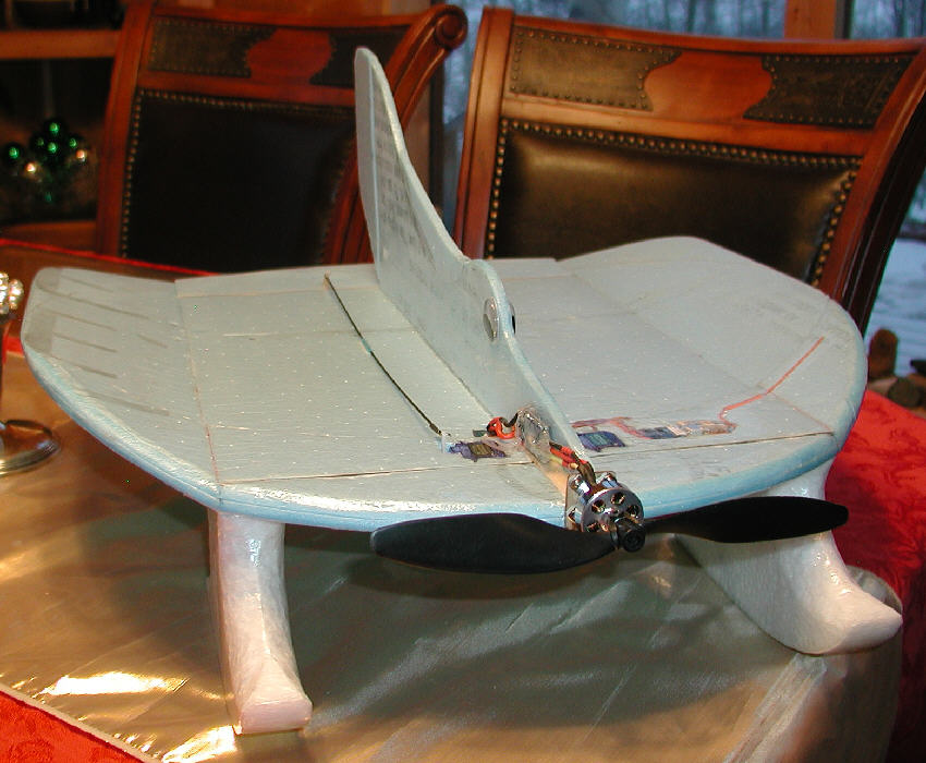
(Below:) Here's a look at the other Flirt variant ready to fly on 1/32" birch ply skis after the modification of the wing tip panels, the extension of the rudder below the wing, and the addition of the battery enclosure. You can also see the three under-tail fins which keep the elevons up off the ground, and protect the extended rudder's lower end from ground strike damage.

Nov. 26, 2010: Winds did really rude things to my snow this week... On Wednesday afternoon, when I didn't have time to get out to fly, there was a nice smooth 3 to 4" thick layer of snow across the entire surface of my 'Antelope Flats' flying site (which I'd mowed down fairly short in October.) But the winds were already building strong that day, & howled all night long & all day yesterday. By early afternoon today, when I finally had time to get out to test-fly the EPP float / ski extensions, there was not a single flake left over that entire area... literally all scoured away by the winds!!!
So I went down to the modest-sized local pond instead, where I'd flown the FLIRT wth the EPP float / skis last summer; there was still a fringe of snow around the edges of all of the exposed black ice. And so I did a bit of flying there.
You really don't need much of an area to fly this modest-sized fun flier... it'll do a takeoff run on snow & be ready to jump up into the air in about 12 feet or less! And I did one takeoff run on some longer bare dried grass along the shoreline, outside of the area which had retained snow; it was airborne from that dry grass in about 6 feet!
The vertical stabilizer area is very adequate for the added float extensions, so it's handling easily & responsively. On the snow & ice, the rudder has great authority to run the FLIRT around in tight maneuvers; while the wide stance of these skis offer very good stability... you have to work hard at it to get it to flip, but with too much side winds & a bit too much throttle, it can be done. (Ask me how I verified this?) No big deal- this is one tough fun flier design that's flying at a light weight & wing loading, so a flip is really un-noticed.
It'll loop inside & outside easily & predictably, rolls well with it's elevon control surfaces, and will fly in a high-alpha position, backing up in light winds to be set down at a standstill if you want. It'll maneuver in a very modest amount of flying space, yet if you give it full throttle, It'll get moving out nicely, and handle gusty wind conditions nicely, too (up to a point...) let's face it, at well under a 4 ounce wing loading, it's not a wind ship as such... but with the help of the KF2 variant doubler, it'll hold it's own in gusty conditions, and have fun flirting with the wind in the process!!
The solid EPP float/skis are about as tough & resilient as they come without adding much for weight, and they'll run over rough wind-chopped snow without any problems... no need for a smooth snow surface- just get out there & play with it!!
The C20 1500 Kv motor on a 2S 900 mAH Mystery battery is turning a 7x6 YAMA SF prop, and it has decent power & authority. I'm flying at half throttle a lot of the time when I'm in low & slow, but I fly the throttle control a lot, too. The center panel of the wing is 12" wide, with 4" wide wing tip panels set at 20 degrees. The length is also 20". (I started with a 20" circle, then extended the rear corners to add area there.)
The narrow elliptical KF top doubler panel is 3-1/2" wide at the center. The Elevon maximum width at the center is 2-5/8". The vertical stabilizer is 5-15/16" tall at the hinge line, and the rudder is 2-34" wide at it's maximum. (I'm using three HXT500 servos & a Corona RS410II receiver with the base loaded shortened antenna.
This fun water & snow float flyer will out-maneuver my Snoball, & will fly happily in a fraction of the airspace if necessary... It's a great all-terrain fun flyer. (I like to keep the clear covering on the bottoms of my float/skis in good waterproof condition, so I do not fly mine from dirt, rocks, or pavement... but it's being done with similar aircraft, so I'll leave that up to you.) It is doing fine from dry grass, and is really happy flying from water, snow, & bare ice.
The 20" FLIRT is a fun flier design that's simple to build & fun to fly in a variety of setups & conditions- [without gear, from wheels, or with the Float/skis from water, & snow, ice, or grass.] It's a design which brings together a lot of desirable structural & handling aspects in a relatively simple build.
Keeping it sized & constructed in a form to be rugged enough for all-terrain flying, yet to be light enough to perform well on a 24 gram motor & 2S battery was a primary design concept. (When flying with floats & with the larger 2S 900 battery at 8-5/8 oz., it's only 59% of the 14.5 oz. weight of my 24" Snowball.) The rudder provides great ground /water / snow handling control authority, while the elevons provide precise roll axis control.
Having the center panel width at 60% of total span, with each wing tip panel at 20% of total span, and the wing tips set at 20 degrees dihedral seems to be a good balance for flying with both elevons & rudder. The result is a fun flier which responds well to the rudder for great ground / water handling, and which also rolls fairly axially in the air and can fly inverted easily when using the elevons. (The widened trailing edge of the wing, and the wider % center panel allows for more elevon area.)
Adding the narrow (<19%) elliptical KF2 variant top doubler panel with it's well-shaped leading edge is beneficial from two perspectives; it add structural strength where it's most needed on a float plane, and it improves the handling of the wing at high airspeeds as well as at very low airspeeds. It actually results in adding a virtual low profile lifting camber line aspect to the wing's profile. Lowering the wing's leading edge entry point to roughly 25% of total wing thickness contributes to the wing's pitch stability and control responsiveness compared to a similar planform thin flat plate wing with a symmetrically rounded or square leading edge.
Where the balance is finally set via battery placement is the final factor in adjusting for better high speed handling stability vs. better low speed high-alpha performance capabilities.
[KF Tech Note]: My 29" KF'ed Skyray, with the first of the very effective narrow Elliptical KF variant top doubler panels, expanded my understanding as to how stepped discontinuities can be effectively used on scratch-built foamies. I experimented with reducing the width of the top doubler panel & tapering it's width towards the tips. (The time invested in the extensive shaping of the wing's leading edge is repaid in performance.) The Skyray's wind penetration capabilities & glide performance in strong slope winds, as well as it's low speed handling performance is far beyond my original expectations.]
With raised wing tips, cross-wind handling on the ground / snow / water is always a concern. This is where the wider mounting stance of the EPP float/skis comes into play. The wide stance makes this aircraft much more stable & difficult to be flipped by cross winds than an aircraft with a narrower float mounting stance. This allows for much more irreverent ground / snow / water handling fun!
With the motor mounted right at wing level, the floats have to be tall enough to provide for prop-to-water / ground clearance. But from a handling standpoint, this approach seems to simply fly better than having a motor mounted high above the wing, dealing with the thrust offset, and trying to fly from lower profile floats, as is done on the Snowball design. I fly both, & both are fun, but the flirt rolls better, flies inverted far more easily, & generally has more aerobatic capability- despite those almost 'cartoonish' looking floats underneath!
Bottom line- it handles very well in a variety of flying environments- a great 'all terrain fun flyer' that builds quickly and inexpensively & is easy to transport. And when built with these materials in this manner, it's a fairly tough & resilient aircraft.
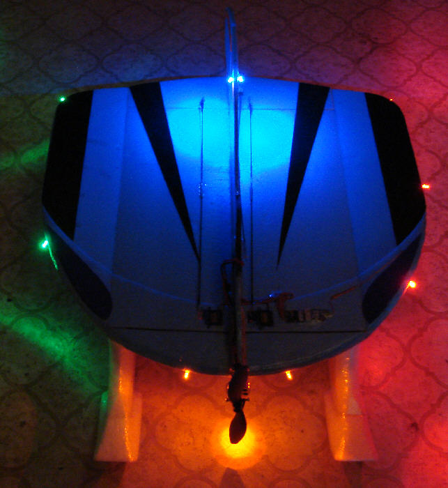
(Dec. 9th, 2010) The FLIRT finally has it's night flying lights installed- just in time to fly the lights for Christmas!
I used discrete 3mm high intensity LEDs in four colors (at up to $.67 each or less) from
http://www.superbrightleds.com
My intention was to add enough high visibility LEDs to see it well for night flying from any direction, flown in any attitude, while keeping the weight gain (and the power requirements) to a minimum. I'm very happy with the results!
When first starting by testing the LEDs to determine the appropriate current dropping resistors that needed to be used which each color of LEDs, I started testing with my adjustable bench power supply set at 5.1 VDC output. I found that I could not light two of either the green or the blue LEDs (wired in series) at this voltage level. (Driving these LEDS individually would require twice the current, so setting them up to be driven in pairs is an advantage.)
When I adjusted the voltage up to about 6.4 volts, I found that I could light two of either the blue or green LEDs in series without using a dropping resistor. I also found that at this voltage level, I could wire in series & light 3 of the superbright red LEDs without a dropper resistor. For the Orange, a series setup of 3 LEDs needed a 47 ohm resistor in series to keep the current at a reasonable level (16.3 mA).
[By basing this setup on the 5 cell 1/4 AAA battery supply, only one 1/4 watt resistor is needed in series with the three orange LEDs; no others are needed.]
2 Blue 3mm LEDs used: RL3-B2030 @ 16.0 mA
2 Green 3mm LEDs used: RL3-G4518 @ 18.2 mA
3 Red 3mm LEDs Used: RL3-R4545 @ 12.9 mA
3 Orange 3mm LEDs Used: RL3-O3214 @ 16.3 mA
My present lighting battery choiceas are either a 1 ounce 5 cell NiMH 170 mAH pack, or a 3/4 ounce 5 cell 1/4 AAA NiMH pack made from the cells within a 9 volt transistor battery.
I kept the LED wires full length in most cases, as I could then orient the LEDs in their positions and mount them by simply taping the stiff wire leads in place against the foam wing.
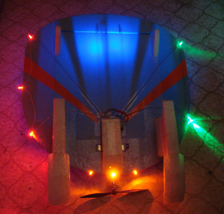
The results are seen in these photos, photographed in subdued lighting; they certainly are plenty bright for night flying purposes, yet are drawing a total of only 63.4 mA on a fully charged battery. (These high intensity LEDs do not need to be driven at the maximum allowable current of 20 mA each to produce a lot of output- they have very high output ratings- especially the red ones!)
With a 2S 500 mAH LiPo motor battery installed and the 1 ounce lighting battery onboard, flying weight is at 9-1/4 ounces. By using the 5 cell 1/4 AAA battery from the chopped 220 MAH 9 volt battery, the weight is reduced by another 1/4 ounce. Sure, many aircraft can easily a lot more added weight... but the kighter the aircraft is, the slower & more irreverently in can be flown, and for night flying, that's really nice, too!
The actual 10 LED array and the associated wiring installation adds only 1/4 ounce to the airframe weight, and a significant portion of that is the clear Scotch tape used to overlay all of the wiring. (I used salvaged ~28 gauge wire from an old parallel printer cable for my wiring.)
[Keep in mind that, unlike LiPo batteries, NiMH batteries do not suffer from deep discharge. That's one of the reasons I like to use them for lighting systems independent power. ]
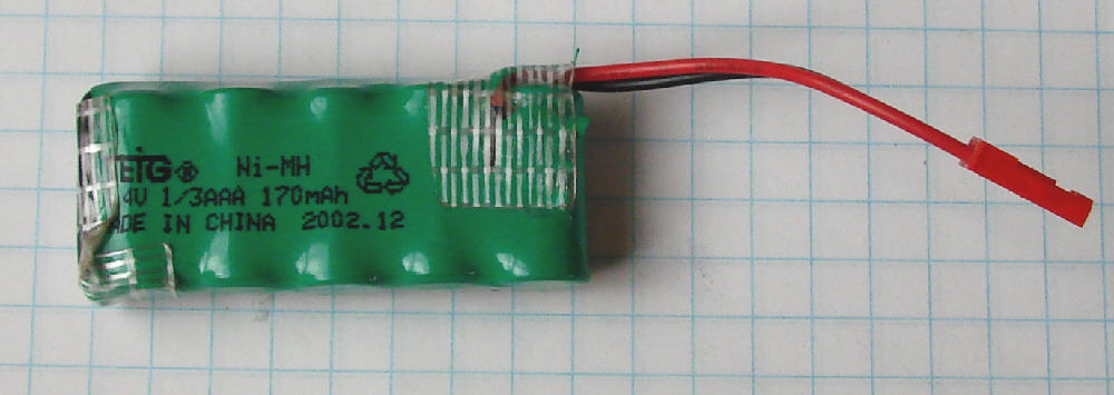
My 5 cell 1/3AAA battery pack I built up for powering the LED array independently weighs 1 ounce, and is a bit bulkier than necessary. But I had some on hand, so I might as well use them.
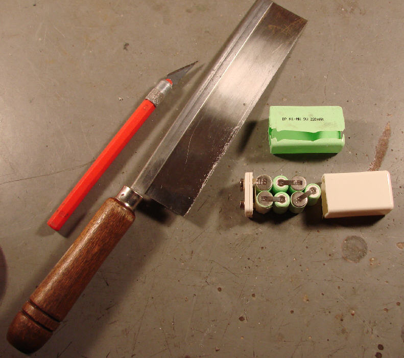
By using 5 cells from a NiMH 9 volt 'transistor' battery, the weight of the lighting battery could be reduced even further to about 3/4 ounce, and the size of the battery pack can be reduced. The Turnigy NiMH '9 volt transistor' battery, available from http://www.allelectronics.com, is rated at 250 mAH- this offers good energy density in a lightweight cell. The pale green covered BP battery shown in the photo below is rated at 220 mAH. I bought this battery from http://www.circuitspecialists.com
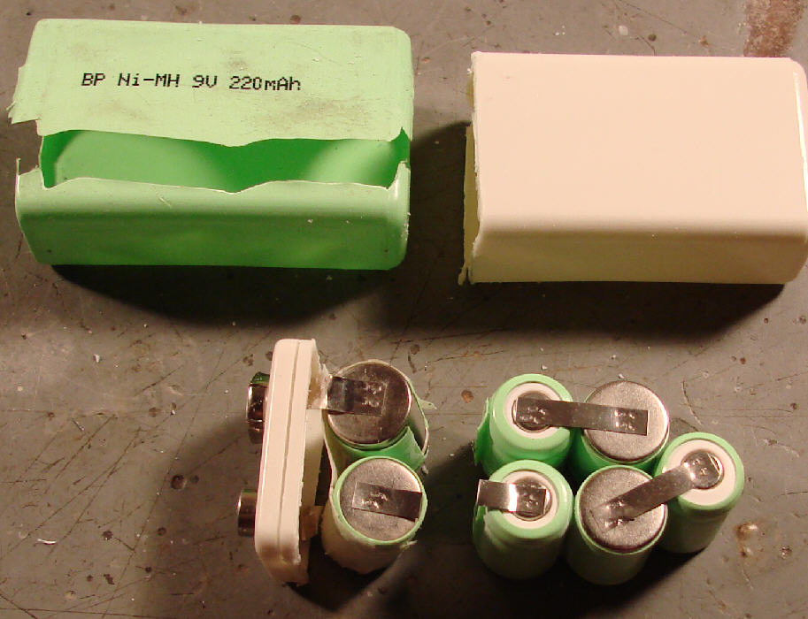
These 9 volt batteries have plastic cases which are glued closed. After cutting away the outer shrink-wrap cover, you can open the case by carefully cutting with a Zona Saw about 3/32" below the glue joint.
Inside are 7 small individual 1/4 AAA size cells, connected in series. I use a razor knife to separate the two cells closest to the terminals, cutting the cell covering shrink wrap on the end two cells, & keeping the shrink wrap undamaged on the 5 cells which I want to use. I then cut the metal straps which inter-connect the cells, leaving me with a 5 cell battery.
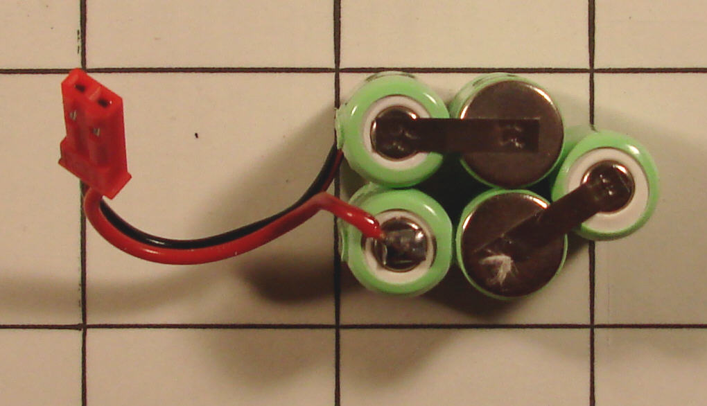
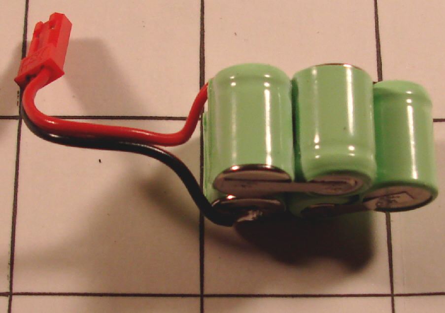
Next I add a JST battery lead, soldering the wires to the remains of the cut-off cell interconnection metal straps. The resulting battery is laid on a 1" grid in the photos below to give you an idea of the size.
This battery will fit inside my battery compartment on the flirt better than the larger flat 5 cell AAA battery does, so the battery will not chill down during cold winter night flying sessions... (Keep in mind that cold batteries drop off in voltage & current delivery capabilities, which will result in noticeably dimming LED lights if the battery is left out in the cold.)
The final result is a 1/4 ounce lighting system which will keep an aircraft brightly lit for up to three hours on one 3/4 ounce battery. (And, of course, the FLIRT can be flown in daylight conditions with only the 1/4 ounce weight gain over what it weighted before the LEDs were installed.
The four photos below tell the story nicely.
I plugged in the smaller 3/4 ounce battery into the LED array connector after charging, at 9:53 AM. After three hours, the blue LEDs (which are mounted up high on the sides of the vertical stabilizer, pointing down to illuminate the top of the wing & the V. Stab.) were beginning to glow a bit dimmer than on the freshly charged pack, while the Reds, Greens, & front Orange LEDs were still very bright.
After four hours (at 1:53 PM) the Red, Green, and Orange LEDs were all still very bright- very good for night flying. The Blue LEDs were noticeably dim at that point. So I called it a very good checkout run for the LEDs, and disconnected the battery. (I'll very likely NEVER do a 3+ hour night flying session... but it's good to know that if I want to pass off the transmitter to a friend for a while to let them try their hand at night flying, the light battery will certainly last through several motor battery runs!